
User's Manual


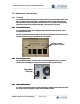


Table Of Contents
- 1 INTRODUCTION
- 2 OneRAN Pilot Station Safety and Compliance Information
- 3 OneRAN Pilot Station System Introduction
- 4 OneRAN Pilot Station Components
- 5 OneRAN Pilot Station Interface Cabling
- 6 OneRAN Pilot Station Frequency Setting Procedures
- 7 OneRAN Pilot Station Installation Procedures
- 7.1 Installation Verification
- 7.2 OneRAN Pilot Station Install Procedures
- 7.3 System Test
- 7.3.1 PC to OneRAN Pilot Station cable
- 7.3.2 System Certification Tests
- 7.3.2.1 Test Case #1 - Image/PLD loading
- 7.3.2.2 Test Case #2 – System Check
- 7.3.2.3 Test Case #3 – Tx check
- 7.3.2.4 Test Case #4 – Output power
- 7.3.2.5 Test Case #5 – GPS Check
- 7.3.2.6 Test Case #6 – BTS Alarm Check
- 7.3.2.7 Test Case #7 – System Reset
- 7.3.2.8 Test Case #8 – PN Check
- 7.3.2.9 Test Case #9 – System Interface Check
- 7.3.3 Operation Tests
- 7.3.4 Operator Specific Tests
- 7.4 Site Clean up and Customer Signoff
- 7.5 Required Tools and Supplies
- 7.6 Troubleshooting Procedures
- 8 Appendix A - Acronyms
- 9 Appendix B - Site preparation checklist
- 10 Appendix C - Installation Checklist
- 11 Appendix D - Customer Certification Document

OneRAN Pilot Station System Installation Manual
____________________________________________________________________________
_____________________________________________________________________________
AirWalk Proprietary and Confidential Page 5 of 49
1 INTRODUCTION
1.1 Proprietary Information Notice
THIS DOCUMENT IS THE PROPERTY OF AIRWALK COMMUNICATIONS, INC. THE
RECIPIENT MAY USE IT ONLY FOR THE PURPOSE FOR WHICH IT WAS
TRANSMITTED AND WILL BE RETURNED UPON REQUEST OR WHEN NO LONGER
NEEDED BY RECIPIENT. IT MAY NOT BE COPIED OR COMMUNICATED WITHOUT
THE WRITTEN CONSENT OF AIRWALK COMMUNICATIONS, INC.
1.2 Purpose of Document
The purpose of this document is to define the Installation, Maintenance and Safety
Compliance of AirWalk Communication’s, Inc. unique CDMA Radio Access Network
(RAN) system. The AirWalk RAN is a market ready, standards compliant, high channel
capacity, cost effective, modular and expandable wireless radio access network system.
Designed specifically for CDMA2000 networks, the Base Station Transceiver (BTS) and
Base Station Controller (BSC) are integrated into a single compact platform.
The target market and applications are corporations, corporate campuses, enterprises,
university campuses, large industrial plants, stadiums, airports, shopping malls, blind
spots, hot spots, rural areas, neighborhoods, and highways.
1.3 Scope
The scope of this document covers the description, environmental specifications,
equipment location, cabling, system installation and maintenance of the AirWalk RAN.
The information contained in this manual was previously included in the combined
Installation & Maintenance Manual for the MiniCell and Pilot Beacon products.
1.4 Order of Precedence
This System Installation Manual will take precedence over any previous AirWalk System
Installation Manual or Document.
1.5 Terminology
See the section entitled: Appendix A - Acronyms
1.6 Applicable Documents
The following documents are applicable to the extent specified in this System Installation
Manual.
1.6.1 AirWalk Documents
• IP- Base Station (BS) System Description.
• IP- Base Station (BS) CPIB Block Diagram.
• IP- Base Station (BS) GPSR Block Diagram.
• IP- Base Station (BS) PCPM Block Diagram.
• IP- Base Station (BS) XCVB Block Diagram.