
User's Manual


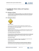
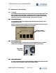


Table Of Contents
- 1 INTRODUCTION
- 2 OneRAN Pilot Station Safety and Compliance Information
- 3 OneRAN Pilot Station System Introduction
- 4 OneRAN Pilot Station Components
- 5 OneRAN Pilot Station Interface Cabling
- 6 OneRAN Pilot Station Frequency Setting Procedures
- 7 OneRAN Pilot Station Installation Procedures
- 7.1 Installation Verification
- 7.2 OneRAN Pilot Station Install Procedures
- 7.3 System Test
- 7.3.1 PC to OneRAN Pilot Station cable
- 7.3.2 System Certification Tests
- 7.3.2.1 Test Case #1 - Image/PLD loading
- 7.3.2.2 Test Case #2 – System Check
- 7.3.2.3 Test Case #3 – Tx check
- 7.3.2.4 Test Case #4 – Output power
- 7.3.2.5 Test Case #5 – GPS Check
- 7.3.2.6 Test Case #6 – BTS Alarm Check
- 7.3.2.7 Test Case #7 – System Reset
- 7.3.2.8 Test Case #8 – PN Check
- 7.3.2.9 Test Case #9 – System Interface Check
- 7.3.3 Operation Tests
- 7.3.4 Operator Specific Tests
- 7.4 Site Clean up and Customer Signoff
- 7.5 Required Tools and Supplies
- 7.6 Troubleshooting Procedures
- 8 Appendix A - Acronyms
- 9 Appendix B - Site preparation checklist
- 10 Appendix C - Installation Checklist
- 11 Appendix D - Customer Certification Document

OneRAN Pilot Station System Installation Manual
____________________________________________________________________________
_____________________________________________________________________________
AirWalk Proprietary and Confidential Page 9 of 49
2.4 Labeling
2.4.1 Grounding
Proper grounding is recommended to ensure good RF performance in addition to
personnel safety. Antenna systems should also be suitably grounded for good RF
performance.
recommended to ensure good RF performance in addition to
personnel safety. Antenna systems should also be suitably grounded for good RF
performance.
Grounding connection points on the chassis are identified by this symbol: Grounding connection points on the chassis are identified by this symbol:
2.4.2 Label: Model Identification, FCC Identification, Power 2.4.2 Label: Model Identification, FCC Identification, Power
The following diagram illustrates the location of the FCC label that will be applied to the
OneRAN Pilot Station unit to provide model identification, FCC identification and rated
power supply information.
The following diagram illustrates the location of the FCC label that will be applied to the
OneRAN Pilot Station unit to provide model identification, FCC identification and rated
power supply information.
1.0
15.0