YAZE218 Indoor Units Outdoor Units AWSI-HJD009/012-N11 AWSI-CNE009/012-N11 AWSI-SXE009/012-N11 AWAU-YAZE218-H11 AWSI-DLF009/012-N11 REFRIGERANT HEAT PUMP R410A MAY-2013 SM YAZE218 1-A.
Table of Contents 1. INTRODUCTION .............................................................................................................................. 1-1 2. PRODUCT DATA SHEET ................................................................................................................ 2-1 3. RATING CONDITIONS .................................................................................................................... 3-1 4. OUTLINE DIMENSIONS ............................................
1—INTRODUCTION 1. INTRODUCTION 1.1 General The YAZE218 is a multi-tubing system with two connected indoor units. The multi-split inverter is a high-level technology product for residential and commercial application offering comfort, low noise operation and energy saving. 1.2 Main Features 1.2.1 High Technology ● Sine wave form for compressor driving. ● DC-BL-SL (Sensor less) Inverter Compressor drive. ● High-speed MCU calculation for accurate Sine wave control. 1.2.2 ● Smart PFC control.
1—INTRODUCTION 1.5 Matching Table INDOOR UNITS AWSI-HJD009-N11 AWSI-HJD012-N11 AWSI-CNE009-N11 AWSI-CNE012-N11 AWSI-SXE009-N11 AWSI-SXE012-N11 AWSI-DLF009-N11 AWSI-DLF012-N11 1.6 Indoor Unit combinations YAZE218 Unit A Unit B Code Sum 25 25 2 25 35 2.5 35 35 3 Nominal Indoor Units Combination SM YUDE 1-A.
2—PRODUCT DATA SHEET 2. PRODUCT DATA SHEET 2.
2—PRODUCT DATA SHEET 2.2 Indoor Units Data 2.2.1 AWSI-HJD009-N11 AWSI-HJD009-N11 Model Indoor Unit Installation Method of Pipe Flared Power supply V/Ph/Hz Fan type & quantity INDOOR Cross ow x 1 Fan speeds H/M/L RPM 1050/900/800 Air ow (1) H/ M / L m3/hr 530/430/330 M in Pa 0 Sound power level (2) H/M/L dB(A) 51/ 47 /39 Sound pressure level(3) H/M/L dB(A) 39/ 34 /26 Moisture removal l / hr 1 Condenstate drain tube I.D mm 16 WxHxD mm 810x285x210 kg 11.
2—PRODUCT DATA SHEET 2.2.3 AWSI-CNE009-N11 AWSI-CNE009-N11 Model Indoor Unit Installation Method of Pipe Flared Power supply V/Ph/Hz Fan type & quantity INDOOR Centrifugal x 1 Fan speeds H/M/L RPM 550/500/450 Air ow (1) H/ M/ L m3/hr 420/370/320 M in Pa 0 Sound power level (2) H/ M/ L dB(A) 49 Sound pressure level(3) H/ M/ L dB(A) 32/30/28 Moisture removal l / hr 0.7 Condenstate drain tube I.D mm 20 mm 575X575X219(625X625X40/725X725X40) kg 12.9(2.2/2.
2—PRODUCT DATA SHEET 2.2.5 AWSI-SXE009-N11 AWSI-SXE009-N11 Model Indoor Unit Installation Method of Pipe Flared Power supply V/Ph/Hz Fan type & quantity INDOOR Centifugal x 2 Fan speeds H/M/L RPM 760/670/500 Air ow (1) H/ M/ L m3/hr 40 0/3 5 0/3 0 0 M in Pa 0 Sound power level (2) H/M/L dB(A) 54/49/41 Sound pressure level(3) H/M/L dB(A) 42/37/29 Moisture removal l / hr 1 Condenstate drain tube I.
2—PRODUCT DATA SHEET 2.2.7 AWSI-DLF09 DCI AWSI-DLF09-DCI Model Indoor Unit Installation Method of Pipe Flared Power supply V/Ph/Hz Fan type & quantity INDOOR Centifugal x 2 Fan speeds H/M/L RPM 920/810/740 Air ow (1) H/M/L m3/hr 620/560/490 M in - M a x Pa 0 -30 Sound power level (2) H/M/L dB(A) 50/47/44 Sound pressure level(3) H/M/L dB(A) 29/26/23 l / hr 0.5 External static pressure Moisture removal Condenstate drain tube I.
3—RATING CONDITIONS 3. RATING CONDITIONS Rating conditions in accordance with ISO 5151 and ISO 13253 (for ducted units). Cooling: Indoor: 27°C DB 19°C WB Outdoor: 35°C DB Heating: Indoor: 20°C DB Outdoor: 7°C DB 6°C WB 3.1 Operating Limits Cooling Heating Voltage Indoor Outdoor Upper limit 32°C DB 23°C WB 46°C DB Lower limit 21°C DB 15°C WB -10°C DB Upper limit 27°C DB 24°C DB 18°C WB Lower limit 10°C DB -15°C DB -16°C WB 1PH 198 – 264 VAC 3PH N/A SM YAZE218 1-A.
4—OUTLINE DIMENSIONS 4. OUTLINE DIMENSIONS 4.1 Indoor Unit: HJD009/012 4—1 | SM YAZE218 1-A.
4—OUTLINE DIMENSIONS 4.2 Indoor Unit: CNE009/012 Unit Model Main unit A Insulation B Front Step C Front width D Front height E Effective Height H 25/35 219 2 9 625/725 40 230 SM YAZE218 1-A.
4—OUTLINE DIMENSIONS 4.3 Indoor Unit: SXE009/012 4.4 OUTDOOR UNIT : YAZE218 4—3 | SM YAZE218 1-A.
5—PERFORMANCE DATA 5. PERFORMANCE DATA 5.1 Outdoor Unit YAZE218 DCI Combinations 5.1.1 operating Indoor model Cooling C apac i t y A B Nom. Powe r C o nsum pt i o n [ W ] Min. Max. Nom. Min. Max. COP Nominal Energy Ef ciency Class 9 2500 2500 1200 3600 700 420 1000 3.57 A 12 3500 3500 1200 4300 1000 420 1200 3.50 A 9+9 2500 5000 1800 6000 1470 550 2100 3.40 A 2500 9+12 2140 2860 5000 1800 6300 1470 550 2130 3.
5—PERFORMANCE DATA 5.2 HJD009 5.2.1 Cooling Capacity Factors - Unit A,B 230[V] : Indoor Fan at High Speed. ID COIL ENTERING AIR DB/WB TEMPERATURE [ºC] OD COIL ENTERING AIR DB TEMPERATURE [ºC] -10 - 20 (protection range) DATA 30 35 40 46 SC 80 - 105 % of nominal PI 25 - 5 0 % of n o m i na l 0.97 1.03 1.09 29/21 32/23 1.16 1.22 SC 1.01 1.03 1.05 1.07 1.09 PI 0.79 0.80 0.82 0.83 0.85 TC 0.92 0.98 1.05 1.11 1.17 SC 0.98 1.00 1.03 1.05 1.07 PI 0.88 0.89 0.91 0.
5—PERFORMANCE DATA 5.2.3 Heating Capacity Factors - Unit A,B 230[V] : Indoor Fan at High Speed. ID COIL ENTERING AIR DB TEMPERATURE [ºC] OD COIL ENTERING AIR DB/WB TEMPERATURE [ºC] -15/-16 -10/-12 -7/-8 -1/-2 2/1 7/6 10/9 15/12 15-24 (Protection Range) DATA 15 20 25 TC PI TC PI TC PI TC PI TC PI TC PI TC PI TC PI TC PI 0.64 0.60 0.71 0.72 0.76 0.82 0.79 0.86 0.81 0.89 1.04 0.94 1.10 1.00 1.16 1.05 0.59 0.66 0.66 0.78 0.72 0.88 0.75 0.92 0.76 0.95 1.00 1.00 1.06 1.06 1.12 1.
5—PERFORMANCE DATA 5.3 HJD012 5.3.1 Cooling Capacity Factors - Unit A,B 230[V] : Indoor Fan at High Speed. ID COIL ENTERING AIR DB/WB TEMPERATURE [ºC] OD COIL ENTERING AIR DB TEMPERATURE [ºC] -10 - 20 (protection range) 25 30 35 40 46 DATA TC SC PI TC SC PI TC SC PI TC SC PI TC SC PI TC SC PI 22/15 0.97 1.01 0.79 0.92 0.98 0.88 0.87 0.96 0.97 0.83 0.93 1.06 0.77 0.90 1.
5—PERFORMANCE DATA 5.3.3 Heating Capacity Factors - Unit A,B 230[V] : Indoor Fan at High Speed. ID COIL ENTERING AIR DB TEMPERATURE [ºC] OD COILENTERING AIR DB/WB TEMPERATURE [ºC] -15/-16 -10/-12 -7/-8 -1/-2 2/1 7/6 10/9 15/12 15-24 (Protection Range) DATA 15 20 25 TC PI TC PI TC PI TC PI TC PI TC PI TC PI TC PI TC PI 0.64 0.60 0.71 0.72 0.76 0.82 0.79 0.86 0.81 0.89 1.04 0.94 1.10 1.00 1.16 1.05 0.59 0.66 0.66 0.78 0.72 0.88 0.75 0.92 0.76 0.95 1.00 1.00 1.06 1.06 1.12 1.
5—PERFORMANCE DATA 5.4 CNE009 5.4.1 Cooling Capacity Factors - Unit A,B 230[V] : Indoor Fan at High Speed. ID COIL ENTERING AIR DB/WB TEMPERATURE [ºC] OD COIL ENTERING AIR DB TEMPERATURE [ºC] -10 - 20 (protection range) 25 30 35 40 46 DATA TC SC PI TC SC PI TC SC PI TC SC PI TC SC PI TC SC PI 22/15 0.97 1.01 0.79 0.92 0.98 0.88 0.87 0.96 0.97 0.83 0.93 1.06 0.77 0.90 1.17 24/17 27/19 29/21 32/23 1.03 1.03 0.80 0.98 1.00 0.89 0.94 0.98 0.99 0.89 0.95 1.08 0.83 0.92 1.
5—PERFORMANCE DATA 5.4.3 Heating Capacity Factors - Unit A,B 230[V] : Indoor Fan at High Speed. ID COIL ENTERING AIR DB TEMPERATURE [ºC] OD COIL ENTERING AIR DB/WB TEMPERATURE [ºC] -15/-16 -10/-12 -7/-8 -1/-2 2/1 7/6 10/9 15/12 15-24 (Protection Range) DATA 15 20 25 TC 0.64 0.59 0.55 PI 0.60 0.66 0.72 TC 0.71 0.66 0.62 PI 0.72 0.78 0.85 TC 0.76 0.72 0.67 PI 0.82 0.88 0.94 TC 0.79 0.75 0.70 PI 0.86 0.92 0.98 TC 0.81 0.76 0.72 PI 0.89 0.95 1.01 TC 1.04 1.00 0.
5—PERFORMANCE DATA 5.5 CNE012 5.5.1 Cooling Capacity Factors - Unit A,B 230[V] : Indoor Fan at High Speed. ID COIL ENTERING AIR DB/WB TEMPERATURE [ºC] OD COIL ENTERING AIR DB TEMPERATURE [ºC] -10 - 20 (protection range) DATA 30 35 40 46 24/17 27/19 TC 80 - 110 % of nominal SC 80 - 105 % of nominal PI 25 - 5 0 % of n o m i na l TC 25 22/15 0.97 1.03 1.09 29/21 32/23 1.16 1.22 SC 1.01 1.03 1.05 1.07 1.09 PI 0.79 0.80 0.82 0.83 0.85 TC 0.92 0.98 1.05 1.11 1.17 SC 0.
5—PERFORMANCE DATA 5.5.3 Heating Capacity Factors - Unit A,B 230[V] : Indoor Fan at High Speed. ID COIL ENTERING AIR DB TEMPERATURE [ºC] OD COIL ENTERING AIR DB/WB TEMPERATURE [ºC] -15/-16 -10/-12 -7/-8 -1/-2 2/1 7/6 10/9 15/12 15-24 (Protection Range) DATA 15 20 25 TC 0.64 0.59 0.55 PI 0.60 0.66 0.72 TC 0.71 0.66 0.62 PI 0.72 0.78 0.85 TC 0.76 0.72 0.67 PI 0.82 0.88 0.94 TC 0.79 0.75 0.70 PI 0.86 0.92 0.98 TC 0.81 0.76 0.72 PI 0.89 0.95 1.01 TC 1.04 1.00 0.
5—PERFORMANCE DATA 5.6 Tubing Length Capacity Correction Factor 5.6.1 Cooling 5.6.2 Heating 5—10 | SM YAZE218 1-A.
6—OPERATING CURVES 6. OPERATING CURVES 6.1 Model: YAZE218 DCI 6.1.1 Cooling – Technician Mode SM YAZE218 1-A.
6—OPERATING CURVES 6.1.2 Heating – Technician Mode 6—2 | SM YAZE218 1-A.
6—OPERATING CURVES 6.1.3 Tubing Length correction Factor SM YAZE218 1-A.
7—ELECTRICAL DATA 7. ELECTRICAL DATA Power Supply Connected to Maximum Current Inrush Current Star ting Current Circuit breaker Power supply wiring no. x cross section Interconnecting cable no. x cross section Note: ● ● 1 PH, 220 -240 VAC, 50Hz Outdoor 13.7 A 35 A 10A 20A 3 X 2.0 mm2 4 X 1.5 mm2 (For each IDU) Inrush current is the current when power is up. (charging the DC capacitors at outdoor unit controller).
8—WIRING DIAGRAMS 8. WIRING DIAGRAMS 8.1 YAZE218 Wiring Diagrams SM YAZE218 1-A.
8—WIRING DIAGRAMS 9. REFRIGERATION DIAGRAMS 9.1 YAZE218 Cooling Mode 9—1 | SM YAZE218 1-A.
8—WIRING DIAGRAMS 9.2 YAZE218 Heating Mode SM YAZE218 1-A.
10—TUBING CONNECTIONS 10. TUBING CONNECTIONS When the outdoor unit is installed above the indoor unit an oil trap is required every 5m along the suction line at the lowest point of the riser. In case the indoor unit is installed above the outdoor, no trap is required. 10—1 | SM YAZE218 1-A.
11—CONTROL SYSTEM 11. CONTROL SYSTEM 11.
11—CONTROL SYSTEM 11.2.6 Temperature Sensors CTT – Compressor Top Temperature OAT – Outdoor Air Temperature OMT– Outdoor middle coil temperature OCT – Outdoor Coil (heat exchanger) Temperature HST – Heat Sink Temperature RGT1..4 – Indoor Unit 1..4 Returned Gas Temperatures RLT 1..4 – Indoor Unit 1..4 Returned Liquid Temperatures 11.2.7 Base Heater Heating element designed to melt any ice that is accumulated on the outdoor unit base during low heating operation. 11.3 General Operating Rules 11.3.
11—CONTROL SYSTEM For Model Q (YBDE018/YAZE218) Total Detected IDU Code (Sum of IDU code) Detected IDU units Minimum Allowed Maximum Allowed 2 2 3 Whenever the sum of the IDU code is outside the range the unit will be forced to Idle Mode and report: “Mismatch between IDU and ODU models”. If the unit is forced to Idle Mode, then it will keep checking this condition (the indoor total capacity test) in order to prevent system latch up.
11—CONTROL SYSTEM 11.3.2.2 ‘Bad Communication’ fault The system keeps a balance of a good/bad communication packet ratio for each active communication channel. When the ratio getting high , system enters ‘Bad Communication’ fault. 11.3.2.3 ‘No Communication’ fault If no legal transmission or no message received for 30 seconds, system enters ‘No Communication’ fault.
11—CONTROL SYSTEM 11.4 Indoor Unit Control 11.4.1 Indoor Fan Control 10 Indoor fan speeds are determined for each model. 5 speeds for each mode cool/dry/fan or heat. When user sets the indoor fan speed to a xed speed (Low/ Medium/ High), unit will operate constantly at set speed. When Auto Fan is selected, indoor unit controller can operate in all speeds. The actual speed is set according to the cool/heat load.
11—CONTROL SYSTEM 11.4.3.2 Indoor Fan Control in Heat Mode Indoor fan speed depends on the indoor coil temperature: 11.4.4 Auto Cool/Heat Mode When in auto cool heat mode unit will automatically select between cool and heat mode according to the difference between actual room temperature and user set point temperature (∆T). Unit will switch from cool to heat when compressor is off for 3 minutes, and ∆T < -3. Unit will switch from heat to cool when compressor is off for 5 minutes, and ∆T < -3. 11.4.
11—CONTROL SYSTEM 11.4.9 11.4.9.1 On Unit Controls and Indicators All Models Except for Floor/Ceiling model STAND BY INDICATOR OPERATION INDICATOR Lights up when the Air Conditioner is connected to power and ready to receive the R/C commands Lights up during operation. Blinks for 300 msec to announce that a R/C infrared signal has been received and stored. Blinks continuously during protections (according to the relevant spec section). TIMER INDICATOR Lights up during Timer and Sleep operation.
11—CONTROL SYSTEM 11.4.9.2 Floor/Ceiling Model STANDBY INDICATOR Lights up when the Air Conditioner is connected to power and is ready for operation OPERATE INDICATOR 1. Lights up during operation. 2. Blinks for 300 msec to announce that a R/C infrared signal has been received and stored. 3. Blinks continuously during protections (according to the relevant spec section). TIMER INDICATOR Lights up during Timer and Sleep operation. FILTER INDICATOR 1. Lights up when Air Filter needs to be cleaned. 2.
11—CONTROL SYSTEM 11.5 Run Mode Run mode is the default operation mode of the system. This is the standard operation mode that is active in eld application (at customer site). System can go from run mode to other operation modes through keyboard or serial ports. 11.5.1 Mode Setting Mode de nes the ODU operation mode.
11—CONTROL SYSTEM 11.5.2.2 Compressor Speed calculation During normal operation (excluding protections), the compressor speed is limited by the following table: 11.5.2.3 Min Speed Cool (check) Max Speed Cool Min Speed Heat Max Speed Heat 20 95 20 95 Indoor Units NLOAD calculation The NLOAD setting is done by the indoor unit controller, based on a PI control scheme.
11—CONTROL SYSTEM 11.5.2.4 Outdoor Unit NLOAD calculation Compressor speed will be set between the minimum speed and the max speed according to the ODU NLOAD 11.5.2.5 11.5.2.5.1 Speed Step Limitations Step 1 and step 2 The compressor speed cannot go below Step1Freq or above Step2Freq during 3 continuous minutes once after the compressor starts up when the ODU unit changes from STBY 11.5.2.5.
11—CONTROL SYSTEM 11.5.3 EEV Control 11.5.3.1 Operation Range The EEV operation range is de ned according to the operation mode as following ODU Mode Normal operation SB IDU inactive Compressor off 400 40 0 COOL 50 to 480 0 HEAT 50 to 480 50 to 120 11.5.3.2 Reaching target value rules For all cases except at EEV initialization procedure, each EEV can move no more than 20 steps at a time.
11—CONTROL SYSTEM 11.5.3.8 Accumulative correction value storage For each combination of active IDUs, the accumulated EEV correction value (for each IDU) will be stored in the memory. Default correction values after power up are zero. 11.5.4 Outdoor Fan Speed Control The OFAN operation keeps the outdoor heat exchanger temperature within a prede ned values by increasing or reducing the OFAN speed. Whenever the OFAN speed is abnormal, the OMT and OCT sensors need to be checked. 11.5.4.
11—CONTROL SYSTEM 11.5.7 Thermodynamic Protections Protection level de nition Five protection levels are de ned: Normal – No protection status is ON. Stop-Rise (SR) – System is in protection, rst level D1 - System is in protection, second level D2 - System is in protection third level Stop-Compressor (SC) – System is in protection fourth level 11.5.8 IDU Protection Level The overall protection level of the indoor units will be the worst protection status among the all indoor units. 11.5.
11—CONTROL SYSTEM 11.5.10 ODU Protections There are 3 ODU protections: ● Compressor overheating ● Heat sink overheating ● System over power Operation logic of all protections is the same. The controlled input (CTT, HST, or PWR) is controlled by changing the protection level using the fuzzy logic algorithm according the input level and the change rate. There are two sets of POWER values, the selection of the values are set according to the state of the Power-Shed dry contact input.
11—CONTROL SYSTEM 11.5.11.2 Deicing Protection Procedure 11.5.11.3 Condensate Water over Flow Protection Each of the pins P1, P2, P3 can have two options: 1 – When it is shorted with P4 0 – When it is not shorted to P4 11.5.11.4 3 Levels Logic (used in oor/ceiling models) 11—16 | SM YAZE218 1-A.2 GB P2 P3 Level 0 0 L0 1 0 L1 1 1 L2&3 0 1 L4 SM YAZE218 1-A.
11—CONTROL SYSTEM 11.5.11.5 1 Level Logic (used in all models except for oor/ceiling models) P2 P3 Level Don’t care 1 Normal Don’t care 0 Over ow SM YAZE218 1-A.
11—CONTROL SYSTEM 11.6 Installation Test Mode 11.6.1 11.6.2 Test Objectives ● Find tube-communication wires mismatch. ● Instruct the technician to match the tubes to the communication wires. ● Find EEV or tubing problems. Test Concept ● The unit will open each EEV separately in cooling mode. ● Detect a temperature drop on the indoor unit. ● Based on the temperature drop, the system can match the tube to the indoor unit. 11.6.
11—CONTROL SYSTEM 4. During the test, the unit will show count down counter (in minutes). The test maximum time is 20 minutes. 5. When the test is nished, the system will show the test result, pass or fail. 6. You can scroll the menu to observe: a. Observe the matrix result b. Guide for problem correction. 7. For xing problem, copy on paper the results displayed results, power off the unit, and then x the problem accordingly.
11—CONTROL SYSTEM 11.6.6 Faults during the test Upon the following, the system will terminate installation test: Fault (display) Reasons ‘OAT’ blink Outdoor ambient temperature is too clod, cannot run installation test. ‘IDU’ blink The selected number of the installed indoor units by the technician does not match the number of indoor units detected by the system. Display indoor or outdoor fault as in diagnostics Check indoor and outdoor diagnostics.
11—CONTROL SYSTEM 11.6.7 Matrix Table Test Result (tbl) & Problem Correction (Crt) The technician has to use labels on the indoor wires connected to the outdoor On unit Label CA CB (CC) (CD) x=Wire name (Marked by technician) 1 2 3 4 For non connected indoor units, there is no need for label. The result is presented in the following way: Present for 2 sec Present for 2 Sec.
11—CONTROL SYSTEM Examples: # 1.
11—CONTROL SYSTEM 11.6.
11—CONTROL SYSTEM 11.7 Technician Test Mode This test is aimed for the technicians to check the system under a preset compressor and outdoor fan values while the expansion valves will function according to the normal running mode. 11.7.1 11.7.2 Entering technician mode o This mode is entered through the outdoor unit using the HMI (refer to user interface section). o It can be selected either for cool or heat. o Technician test is not possible to enter during deicer.
11—CONTROL SYSTEM 11.8 11.8.1 User Interface User interface description o The user interface uses three 7 segments, and 4 keys. o o Keys, The 4 keys are: — Scroll - used to scroll between options (up and down) — Select - use to select an option — Escape - Will go up one level in the menu The user interface concept is Tree menus. o Active selection or status will be indicated by blinking the display. 11.8.2 Keys functionality o Scrolling will be done whenever the button is pressed.
11—CONTROL SYSTEM 11.8.3 Menus 11.8.3.1 Main Menu Notes: 1. The default presentation will be alternating repeatedly among the following for single and multi split units: o the mode of the unit (Cl/Ht/Sb) shown for 2 sec. o (‘id’ + the number of communicative IDUs number) shown for 2 sec. o Active fault (among ODU or IDUs), each to be shown for 2 sec. 2. In diagnostics menu: o xx means failure code. 11—26 | SM YAZE218 1-A.
11—CONTROL SYSTEM o Maximum 5 faults are presented for each unit (each IDUs/ODU). When no faults “-- “ sign will be shown. o The active faults have higher priority for presentation than non active ones. o Non active faults are presented according to their chronological order, starting from the latest one. o Whenever a new active fault occurs, it will be presented immediately. o Active faults are blinking, where non active ones do not. 3.
11—CONTROL SYSTEM 11.8.3.
11—CONTROL SYSTEM Notes: o For the temperature display, when a thermistor is shorted, disconnected show FLT, when it’s disabled show DIS. o It is possible to present a number between 999 and 99,999 by alternating between two numbers (each number is presented for 1 second). The two numbers format is (off)xx, yyy. o The compressor time is measured in hour’s units. o The modes: Cool, Heat, Dry, Fan Auto will be presented: CL, Ht, dr, FAn, AUt. o The current is the AC current of the unit.
11—CONTROL SYSTEM 11.10 System Parameters 11.10.1 General parameters # Name Default Value Units # Name Default Value Units 1. MinOFFTime 3 minute 35. DEICT2 36 second 2. MinONTime 3 minute 36. DEICT3 6 second 3. HzUp_CTTOH 2 / 60 /8 Hz / Sec/NA 37. DSTF 12 °C 4. HzDown1_CTTOH -2 / 60 /5 Hz / Sec/NA 38. OMTOH0 50 °C 5. HzDown2_CTTOH -4 / 60 /3 Hz / Sec/NA 39. OMTOH1 53 °C 6. HzDown1_CCROC -1 / 2 /1 Hz / Sec/NA 40. OMTOH2 56 °C 7.
11—CONTROL SYSTEM 11.10.2 ODU Model Dependent Parameters # Name Q YAZ218 1. 2. 3. 4. 5. 6. 7. 8. 9. 10. 11. 12. 13. 14. 15. 16. 17. 18. 19. 20. 21. 22. 23. 24. 25. 26. 27. 28. 29. 30. 31. 32. 33. 34. 35. 36. 37. 38. 39. 40. 41. 42. 43. 44. 45. 46. 47. 48. 49. 50. 51. 52. 53.
11—CONTROL SYSTEM # 102. Name EEV_OL_Beta3_S_C Q YAZ218 Unit -2.734 103. EEV_OL_ Gamma3 _S_C 1.714 104. EEV_OL_Delta3 _S_C -38 # 131. Name EEV_OL_ Gamma _M3_C Q YAZ218 NA Unit NA 132. EEV_OL_Delta _M3_C NA NA NA 133. EEV_OL_Alpha_M4_C NA NA 105. EEV_OL_Alpha1_S_H 0 NA 134. EEV_OL_Beta_M4_C NA NA 106. EEV_OL_Beta1_S_H 3.308 NA 135. EEV_OL_ Gamma _M4_C NA NA 107. EEV_OL_ Gamma1_S_H 1.378 NA 136. EEV_OL_Delta_M4_C NA NA 108. EEV_OL_Delta1_S_H 26 NA 137.
11—CONTROL SYSTEM 11.10.3 Indoor Units SW Parameters 11.10.3.
12—TROUBLESHOOTING 12. TROUBLESHOOTING WARNING!!! When Power Up – the whole outdoor unit controller, including the wiring, is under HIGH VOLTAGE!!! Never open the Outdoor unit before turning off the Power!!! When turned off, the system is still charged (400V)!!! It takes about 1 Min. to discharge the system. Touching the controller before discharging may cause an electrical shock!!! For safe handling of the controller, please refer to section 12.5 below. 12.
12—TROUBLESHOOTING No SYMPTOM PROBABLE CAUSE CORRECTIVE ACTION - Repair if needed 10. 11. Compressor operates but one or more units generates no capacity Compressor is over heated and unit does not generate capacity PFC Chock coil Check the PFC Chock coil Burnt fuse Check 20A fuse on the Filter (12.4.2) EEV problem Check EEV (12.4.5) Refrigerant leakage Check refrigeration system (12.
12—TROUBLESHOOTING 12.3 12.3.1 Diagnostics Fault Code for Outdoor unit The last fault occurred in the system will be stored in the EEPROM. If no fault exist in the system, no fault code will be displayed during normal operation mode. For single Split units only, when system enters diagnostics mode (through IDU communication), the last fault code will be displayed even if the system has recover from that fault.
12—TROUBLESHOOTING 12.3.2 No Outdoor unit diagnostics and corrective actions Fault Name 1 OCT bad 2 CTT bad 3 HST bad 4 OAT bad 5 OMT bad 6 RGT bad 7 RLT bad 8 Reser ved Fault Description Corrective Action Thermistor not connected or damaged Check Thermistor (12.4.
12—TROUBLESHOOTING No Fault Name Fault Description Corrective Action 20 Heat sink Over Heating Compressor stopped due to heatsink protection Check that the air ow around the ODU is free and the fan is running free.
12—TROUBLESHOOTING 12.3.3 DMSMP diagnostics The DMSMP system has 4 IDU LEDs, 1 ODU LED, and 1 Power LED. Each communication channel is built up from receiving and transmitting channels. The outdoor controller is the master of communication (always initiated communication) while the DMSMP and indoor are slave (responds only when it receives). Channel LED Ri has communication The relevant LEDi will be ON. Ri has no communication The relevant LEDi will be Off.
12—TROUBLESHOOTING 12.3.4 Fault Code for Indoor unit Pressing Mode button for long will activate diagnostic mode by the acknowledgment of 3 short beeps and lighting of COOL and HEAT LED’s. When Indoor diagnostics is displayed, all four LED’s (STBY, Operate, Filter, TMR) are on. Entering diagnostics in STBY mode allows only viewing of status (fault-display). In diagnostic mode, system problems / information will be indicated by blinking of Heat & Cool LED’s.
12—TROUBLESHOOTING 12.3.5 Indoor unit diagnostics and corrective actions No.
12—TROUBLESHOOTING 12.4.4 Checking the Reverse Valve (RV) The RV has two parts, Solenoid and valve. Solenoid - Running in heating mode, check the voltage between two pins of reverse valve connector, normal voltage is 230VAC. if no power supply to RV, Check RV operation with direct 230VAC power supply, if OK, replace outdoor controller. Valve — if RV solenoid is OK (as above) but still no heating operation while compressor is On, replace the valve. 12.4.
12—TROUBLESHOOTING 12.4.8.2 EMC troubles to near by home appliances Locations most susceptible to noise: 1. A television or radio is located near the A/C and A/C wiring. 2. The antenna cable for a television or radio is located close to the A/C and A/C wiring. 3. Locations where television and radio signals are weak. Trouble: 1. Noise appears in the television picture, or the picture is distorted. 2. Static occurs in the radio sound. Correction: 1. Select a separate power source. 2.
13—EXPLODED VIEWS AND SPARE PART LISTS 13. EXPLODED VIEW AND SPARE PART LIST 13.1 Multi YAZE218 – Exploded View 13—1 | SM YAZE218 1-A.
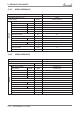
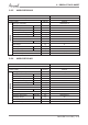
13—EXPLODED VIEWS AND SPARE PART LISTS 13.2 Multi YAZ218 DCI – Spare Part List I t em Seq.
14—APPENDIX A 14. APPENDIX A INSTALLATION AND OPERATION MANUAL 14—1 | SM YAZE218 1-A.
SERVICE MANUAL YAZE218