SX DCI Series Indoor Units Outdoor Units SX 9 DCI GC 9 DCI SX 12 DCI GC 12 DCI SX 18 DCI GC 18 DCI SX 24 DCI GC 24 DCI SX 30 DCI GC 30 DCI REFRIGERANT R410A SM SX DCI 1-A.
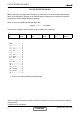
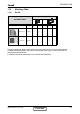
LIST OF EFFECTIVE PAGES LIST OF EFFECTIVE PAGES Note: Changes in the pages are indicated by a “Revision#” in the footer of each effected page (when none indicates no changes in the relevant page). All pages in the following list represent effected/ non effected pages divided by chapters. Dates of issue for original and changed pages are: Original ....... 0 ........ April 2006 Total number of pages in this publication is 88 consisting of the following: Page No. Revision No. # Page No. Revision No.
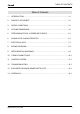
TABLE OF CONTENTS Table of Contents 1. INTRODUCTION ...................................................................................................1-1 2. PRODUCT DATA SHEET ......................................................................................2-1 3. RATING CONDITIONS ..........................................................................................3-1 4. OUTLINE DIMENSIONS........................................................................................4-1 5.
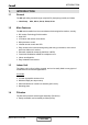
INTRODUCTION 1. INTRODUCTION 1.1 General The SX split ceiling mounted range comprise RC (heat pump) models, as follows: ● Heat Pump 1.2 SX 9, SX 12, SX 18, SX 24, SX 30. Main Features The SX series benefits from the most advanced technological innovations, namely: ● DC Inverter Technology R410A models. ● High COP. ● Low indoor and outdoor noise levels. ● Microprocessor control. ● Infrared remote control with LED.
INTRODUCTION 1.5 Control The microprocessor indoor controller, and an infrared remote control, supplied as standard, providing complete operating function and programming. For further details please refer to the Operation Manual, Appendix A. 1.6 Outdoor Unit The SX outdoor units can be installed as floor or wall mounted units by using a wall supporting bracket. The metal sheets are protected by anti- corrosion paint work allowing long life resistance. All outdoor units are pre-charged.
INTRODUCTION 1.10 Matching Table 1.10.1 R410A INDOOR UNITS OUTDOOR UNITS MODEL REFRIGER. SX 9 SX 12 SX 18 GC 9-12-18 R410A √ √ √ GC 24-30 R410A SX 24 SX 30 √ √ The above table lists outdoor units and SX DCI indoor units which can be matched together. In addition the listed outdoor units can be matched with other types of indoor units such as cassettes and wall mounted. For further information please refer to the relevant Service Manual. SM SX DCI 1-A.
PRODUCT DATA SHEET 2. PRODUCT DATA SHEET 2.
PRODUCT DATA SHEET 2.2 SX 12 DCI R410A Model Indoor Unit SX 12 DCI Model Outdoor Unit GC 12 DCI Installation Method of Pipe Characteristics Flared Capacity (1) Power input (1) EER (Cooling) or COP(Heating) (1) Energy efficiency class Units Cooling Heating Btu/hr 11940(5120~15010) 14330(5120~17060) kW 3.5(1.5-4.4) 4.2(1.5~5.0) kW 0.98(0.46-1.3) 1.31(0.35~1.58) W/W 3.57 3.
PRODUCT DATA SHEET 2.3 SX 18 DCI R410A Model Indoor Unit SX 18 DCI Model Outdoor Unit GC 18 DCI Installation Method of Pipe Characteristics Flared Capacity (1) Power input (1) EER (Cooling) or COP(Heating) (1) Energy efficiency class Units Cooling Heating Btu/hr 17000(5120-20460) 20460(5120-24550) kW 5.0(1.5-6.0) 5.8(1.5~7.2) kW 1.65(0.5-2.1) 1.69(0.45-2.1) W/W 3.03 3.
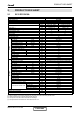
PRODUCT DATA SHEET 2.4 SX 24 DCI R410A Model Indoor Unit SX 24 DCI Model Outdoor Unit GC 24 DCI Installation Method of Pipe Characteristics H/M/L H/M/L Min-Max H/M/L RPM m3/hr Pa dB(A) Flared Cooling Heating 23200(5120~25590) 25910(5110-30000) 6.80(1.50-7.60) 7.60(1.60~8.60) 2.25(0.50-2.68) 2.05(05~2.30) 3.02 3.61 B A 220-240V/Single/50Hz 10.1 9.6 15 45 Centrifugal x 2 1300/1200/1050 1020/930/760 0 67/64/60 H/M/L dB(A) 56/53/49 l/hr mm 2.
PRODUCT DATA SHEET 2.5 SX 30 DCI R410A Model Indoor Unit SX 30 DCI Model Outdoor Unit GC 30 DCI Installation Method of Pipe Characteristics Flared Units Cooling Heating Btu/hr 25570(6820-32390) 30000(5110-35800) kW 7.5(1.6-8.6) 8.4(1.8-9.
RATING CONDITIONS 3. RATING CONDITIONS Standard conditions in accordance with ISO 5151, ISO 13253 (for ducted units) and EN 14511. Cooling: Indoor: 27oC DB 19oC WB Outdoor: 35 oC DB Heating: Indoor: 20oC DB Outdoor: 7oC DB 6oC WB 3.1 Operating Limits R410A Indoor Cooling Heating Voltage SM SX DCI 1-A.
OUTLINE DIMENSIONS 4. OUTLINE DIMENSIONS 4.1 Indoor Unit: SX 9, 12 DCI 4.2 Indoor Unit: SX 18, 24, 30 DCI SM SX DCI 1-A.
OUTLINE DIMENSIONS 4.3 Outdoor Unit: GC 9, 12, 18 DCI 4.4 Outdoor Unit: GC 24, 30 DCI 4-2 CONTENT SM SX DCI 1-A.
PERFORMANCE DATA & PRESSURE CURVES 5. PERFORMANCE DATA 5,1 SX 9 DCI 5.1.1 Cooling Capacity (kW) – Run Mode 230[V] : Indoor Fan at High Speed. ID COIL ENTERING AIR DB/WB TEMPERATURE [oC] OU COIL ENTERING AIR DB TEMPERATURE [oC] DATA TC SC PI TC SC PI TC SC PI TC SC PI TC SC PI TC SC PI -10 - 20 (protection range) 25 30 35 40 46 22/15 24/17 27/19 29/21 32/23 2.42 2.09 0.49 2.30 2.04 0.54 2.18 1.98 0.60 2.07 1.93 0.66 1.93 1.87 0.
PERFORMANCE DATA & PRESSURE CURVES 5.1.3 Heating Capacity (kW) - Run Mode 230[V] : Indoor Fan at High Speed. ID COIL ENTERING AIR DB TEMPERATURE [oC] OU COIL ENTERING AIR DB/WB TEMPERATURE [oC] -15/-16 -10/-12 -7/-8 -1/-2 2/1 7/6 10/9 15/12 15-24 (Protection Range) DATA 15 20 25 TC PI TC PI TC PI TC PI TC 2.04 0.56 2.27 0.67 2.44 0.76 2.53 0.80 2.58 1.75 0.67 1.98 0.79 2.16 0.87 2.24 0.92 2.30 PI 0.83 1.89 0.61 2.12 0.73 2.30 0.82 2.38 0.86 2.44 0.89 TC PI TC PI TC PI TC PI 3.34 0.87 3.53 0.
PERFORMANCE DATA & PRESSURE CURVES 5.1.5 Model: SX 9 DCI Cooling – Test Mode Suction Pressure Vs.Outdoor Temp. Suction Pressure [kPa] 1400 Indoor DB/WB 1300 1200 1100 22/15 1000 24/17 900 27/19 800 29/21 700 32/23 600 500 10 15 20 25 30 35 40 45 Outdoor DB Temperature[ºC ] Discharge Pressure [kPa] Discharge Pressure Vs. Outdoor Temp.
PERFORMANCE DATA & PRESSURE CURVES 5.1.6 Heating – Test Mode Suction Pressure [kPa] Suction Pressure Vs.Outdoor Temp. 1300 1200 1100 1000 900 800 700 600 500 400 300 200 -15 15 20 25 -10 -5 0 5 10 15 Outdoor WB Temperature [ºC] Discharge Pressure [kPa] Discharge Pressure Vs. Outdoor Temp. 4000 3750 3500 3250 3000 2750 2500 2250 2000 1750 1500 1250 1000 -15 Indoor DB 15 20 25 -10 -5 0 5 10 15 Outdoor WB Temperature [ºC] 5-4 CONTENT SM SX DCI 1-A.
PERFORMANCE DATA & PRESSURE CURVES 5.2 SX 12 DCI 5.2.1 Cooling Capacity (kW) - Run Mode 230[V] : Indoor Fan at High Speed. ID COIL ENTERING AIR DB/WB TEMPERATURE [oC] OU COIL ENTERING AIR DB TEMPERATURE [oC] 22/15 DATA -10 - 20 (protection range) 25 30 35 40 46 24/17 27/19 29/21 32/23 TC SC PI TC SC PI TC SC 3.38 2.65 0.77 3.22 2.58 PI 0.86 80 - 110 % of nominal 80 - 105 % of nominal 25 - 50 % of nominal 3.60 3.83 4.05 2.70 2.75 2.81 0.78 0.80 0.81 3.44 3.66 3.88 2.63 2.69 2.74 0.89 0.
PERFORMANCE DATA & PRESSURE CURVES 5.2.3 Heating Capacity (kW) - Run Mode 230[V] : Indoor Fan at High Speed. ID COIL ENTERING AIR DB TEMPERATURE [oC] OU COIL ENTERING AIR DB/WB TEMPERATURE [oC] -15/-16 -10/-12 -7/-8 -1/-2 2/1 7/6 10/9 15/12 15-24 (Protection Range) DATA 15 20 25 TC PI TC PI TC PI TC PI TC 2.67 0.79 2.98 0.95 3.20 1.07 3.32 1.13 3.39 2.49 0.87 2.79 1.03 3.02 1.15 3.13 1.21 3.20 1.25 2.30 0.95 2.60 1.11 2.83 1.23 2.94 1.29 3.02 4.20 1.31 4.01 1.39 4.26 1.46 4.50 1.54 PI 1.
PERFORMANCE DATA & PRESSURE CURVES 5.2.5 Model: SX 12 DCI Cooling – Test Mode Suction Pressure VS.Outdoor Temp. Suction Pressure [kPa] 1400 Indoor DB/WB 1300 22/15 1200 24/17 1100 27/19 1000 29/21 900 32/23 800 700 600 500 10 15 20 25 30 35 40 45 Outdoor DB Temperature[ºC ] Discharge Pressure [kPa] Discharge Pressure VS. Outdoor Temp.
PERFORMANCE DATA & PRESSURE CURVES 5.2.6 Heating – Test Mode Suction Pressure VS.Outdoor Temp. 1300 Suction Pressure [kPa] 1200 1100 1000 900 800 15 700 20 600 25 500 400 300 200 -15 -10 -5 0 5 10 15 Outdoor WB Temperature [ºC] Discharge Pressure [kPa] Discharge Pressure VS. Outdoor Temp. 4000 3750 3500 3250 3000 2750 Indoor DB 15 2500 2250 2000 1750 1500 1250 1000 -15 20 25 -10 -5 0 5 10 15 Outdoor WB Temperature [ºC] 5-8 CONTENT SM SX DCI 1-A.
PERFORMANCE DATA & PRESSURE CURVES Capacity Correction Factor Due to Tubing Length 5.3.1 SX 9, 12 DCI :Cooling Capacity Ratio 5.3 1.01 1.00 0.99 0.98 0.97 0.96 0.95 0.94 0.93 0.92 0.91 3 4 5 6 7 8 9 10 11 12 13 14 15 16 17 18 19 20 Tubing Length [m ] 5.3.2 Heating Capacity Ratio 1.02 1.00 0.98 0.96 0.94 0.92 0.90 3 4 5 6 7 8 9 10 11 12 13 14 15 16 17 18 19 20 Tubing Length [m ] SM SX DCI 1-A.
PERFORMANCE DATA & PRESSURE CURVES 5.4 SX18 DCI 5.4.1 Cooling Capacity (kW) - Run Mode 230[V] : Indoor Fan at High Speed. ID COIL ENTERING AIR DB/WB TEMPERATURE [oC] OU COIL ENTERING AIR DB TEMPERATURE [oC] 22/15 24/17 29/21 32/23 TC SC PI TC SC PI TC SC PI 4.93 3.35 1.25 4.67 3.22 1.42 80 - 110 % of nominal 80 - 105 % of nominal 25 - 50 % of nominal 5.22 5.51 5.80 3.40 3.45 3.50 1.28 1.30 1.33 4.96 5.25 5.54 3.27 3.32 3.37 1.48 1.45 1.50 6.09 3.55 1.36 5.83 3.42 1.53 TC 4.42 4.71 5.00 5.
PERFORMANCE DATA & PRESSURE CURVES 5.4.3 Heating Capacity (kW) - Run Mode 230[V] : Indoor Fan at High Speed. ID COIL ENTERING AIR DB TEMPERATURE [oC] OU COIL ENTERING AIR DB/WB TEMPERATURE [oC] -15/-16 -10/-12 -7/-8 -1/-2 2/1 7/6 10/9 15/12 15-24 (Protection Range) DATA 15 20 25 TC PI TC PI TC PI TC PI TC 2.64 1.18 3.48 1.34 4.12 1.45 4.43 1.51 4.65 1.88 1.35 2.72 1.50 3.36 1.62 3.67 1.68 3.89 PI 1.55 2.26 1.27 3.10 1.42 3.74 1.54 4.05 1.59 4.27 1.63 TC PI TC PI TC PI TC PI 6.18 1.61 6.50 1.
PERFORMANCE DATA & PRESSURE CURVES 5.4.5 Model: SX 18 DCI Cooling – Test Mode Suction Pressure VS.Outdoor Temp. Suction Pressure [kPa] 1400 Indoor DB/WB 1300 1200 1100 22/15 1000 24/17 27/19 900 29/21 800 32/23 700 600 500 10 15 20 25 30 35 40 45 Outdoor DB Temperature[ºC ] Discharge Pressure [kPa] Discharge Pressure VS. Outdoor Temp.
PERFORMANCE DATA & PRESSURE CURVES 5.4.6 Heating – Test Mode Suction Pressure VS.Outdoor Temp. Suction Pressure [kPa] 1100 1000 900 15 800 20 700 25 600 500 400 300 200 -15 -10 -5 0 5 10 15 Outdoor WB Temperature [ºC] Discharge Pressure [kPa] Discharge Pressure VS. Outdoor Temp. 4000 3750 3500 3250 3000 2750 2500 2250 2000 1750 1500 1250 1000 -15 Indoor DB 15 20 25 -10 -5 0 5 10 15 Outdoor WB Temperature [ºC] SM SX DCI 1-A.
PERFORMANCE DATA & PRESSURE CURVES 5.5 Capacity Correction Factor Due to Tubing Length 5.5.1 SX 18 DCI :Cooling 1.01 Capacity ratio 0.99 0.97 0.95 0.93 0.91 0.89 4 6 8 10 12 14 16 18 20 22 24 26 28 30 Tubing length(m ) Heating Capacity ratio 5.5.2 1.02 1.00 0.98 0.96 0.94 0.92 0.90 0.88 0.86 0.84 4 6 8 10 12 14 16 18 20 22 24 26 28 30 Tubing Length(m ) 5-14 CONTENT SM SX DCI 1-A.
PERFORMANCE DATA & PRESSURE CURVES 5.6 SX 24 DCI 5.6.1 Cooling Capacity (kW) - Run Mode 230[V] : Indoor Fan at High Speed. ID COIL ENTERING AIR DB/WB TEMPERATURE [oC] OU COIL ENTERING AIR DB TEMPERATURE [oC] 22/15 24/17 29/21 32/23 TC SC PI TC SC PI TC SC PI 6.70 5.36 1.70 6.35 5.15 1.94 80 - 110 % of nominal 80 - 105 % of nominal 25 - 50 % of nominal 7.09 7.49 7.88 5.44 5.52 5.60 1.74 1.78 1.82 6.75 7.14 7.54 5.23 5.31 5.39 2.01 1.98 2.05 8.28 5.68 1.85 7.93 5.47 2.09 TC 6.01 6.41 6.80 7.
PERFORMANCE DATA & PRESSURE CURVES 5.6.3 Heating Capacity (kW) - Run Mode 230[V] : Indoor Fan at High Speed. ID COIL ENTERING AIR DB TEMPERATURE [oC] OU COIL ENTERING AIR DB/WB TEMPERATURE [oC] -15/-16 -10/-12 -7/-8 -1/-2 2/1 7/6 10/9 15/12 15-24 (Protection Range) DATA 15 20 25 TC PI TC PI TC PI TC PI TC 3.46 1.48 4.57 1.67 5.40 1.81 5.81 1.88 6.09 2.46 1.69 3.57 1.88 4.40 2.02 4.81 2.10 5.09 PI 1.93 2.96 1.58 4.07 1.77 4.90 1.92 5.31 1.99 5.59 2.04 TC PI TC PI TC PI TC PI 8.10 2.00 8.52 2.
PERFORMANCE DATA & PRESSURE CURVES 5.6.5 Model: SX 24 DCI Cooling – Test Mode Suction Pressure [kPa] Suction Pressure Vs. Outdoor Temp. 1000 960 920 880 840 800 760 720 680 640 600 Indoor DB/WB 22/15 24/17 27/19 29/21 32/23 10 15 20 25 30 35 40 45 O Outdoor DB Temperature[ C] Discharge Pressure [kPa] Discharge Pressure Vs. Temp.
PERFORMANCE DATA & PRESSURE CURVES 5.6.6 Heating – Test Mode Suction Pressure Vs. Outdoor Temp. Suction Pressure [kPa] 1050 950 850 Indoor DB 750 15 650 550 20 450 25 350 250 -15 -10 -5 0 5 10 15 O Outdoor WB Temperature[ C] Discharge Pressure [kPa] Discharge Pressure Vs. Outdoor Temp. 3700 3500 3300 3100 2900 2700 2500 2300 2100 1900 1700 Indoor DB 15 20 25 -15 5-18 -10 -5 0 5 O Outdoor WB Temperature[ C] CONTENT 10 15 SM SX DCI 1-A.
PERFORMANCE DATA & PRESSURE CURVES 5.7 Capacity Correction Factor Due to Tubing Length 5.7.1 SX 24 DCI :Cooling 1.01 0.99 Capacity Ratio 0.97 0.95 0.93 0.91 0.89 0.87 0.85 5 Heating Tube Length(m) 5.7.2 6 7 7.5 10 15 20 25 30 Tube Length [m]) 5 6 7 7.5 10 15 20 20 25 25 Heating 1.05 Capacity Ratio 1.00 0.95 0.90 0.85 0.80 0.75 0.70 5 SM SX DCI 1-A.3 GB 6 7 7.
PERFORMANCE DATA & PRESSURE CURVES 5.8 SX 30 DCI 5.8.1 Cooling Capacity (kW) - Run Mode 230[V] : Indoor Fan at High Speed. ID COIL ENTERING AIR DB/WB TEMPERATURE [oC] OU COIL ENTERING AIR DB TEMPERATURE [oC] 22/15 24/17 29/21 32/23 TC SC PI TC SC PI TC SC PI 7.39 5.72 1.88 7.01 5.49 2.14 80 - 110 % of nominal 80 - 105 % of nominal 25 - 50 % of nominal 7.82 8.26 8.69 5.80 5.88 5.97 1.92 1.97 2.01 7.44 7.88 8.31 5.58 5.66 5.75 2.23 2.19 2.27 9.13 6.05 2.05 8.75 5.83 2.31 TC 6.63 7.07 7.50 7.
PERFORMANCE DATA & PRESSURE CURVES 5.8.3 Heating Capacity (kW) - Run Mode 230[V] : Indoor Fan at High Speed. ID COIL ENTERING AIR DB TEMPERATURE [oC] OU COIL ENTERING AIR DB/WB TEMPERATURE [oC] DATA 15 20 25 TC PI TC PI TC PI TC PI TC 3.96 1.78 5.23 2.02 6.18 2.19 6.65 2.28 6.97 2.82 2.04 4.09 2.27 5.04 2.44 5.51 2.53 5.83 PI 2.34 3.39 1.91 4.66 2.14 5.61 2.32 6.08 2.40 6.40 2.46 TC PI TC PI TC PI TC PI 9.27 8.70 2.55 2.42 9.75 9.18 2.47 2.60 10.23 9.66 2.52 2.
PERFORMANCE DATA & PRESSURE CURVES 5.8.5 Model: SX 30 DCI Cooling – Test Mode Suction Pressure [kPa] Suction Pressure Vs. Outdoor Temp. 1000 960 920 880 840 800 760 720 680 640 600 Indoor DB/WB 22/15 24/17 27/19 29/21 32/23 10 15 20 25 30 35 40 45 O Outdoor DB Temperature[ C] Discharge Pressure [kPa] Discharge Pressure Vs.Outdoor Temp.
PERFORMANCE DATA & PRESSURE CURVES 5.8.6 Heating – Test Mode Suction Pressure [kPa] Suction Pressure Vs.Outdoor Temp. 1150 1050 950 850 750 650 550 450 350 250 Indoor DB 15 20 25 -15 -10 -5 0 5 10 15 Outdoor WB Temperature[OC] Discharge Pressure [kPa] Discharge Pressure Vs.Outdoor Temp. 3850 3600 3350 3100 2850 2600 2350 2100 1850 1600 Indoor DB 15 20 25 -15 -10 -5 0 5 10 15 O Outdoor WB Temperature[ C] SM SX DCI 1-A.
PERFORMANCE DATA & PRESSURE CURVES 5.9 Capacity Correction Factor Due to Tubing Length 5.9.1 SX 80 DCI :Cooling 1.01 1.00 Capacity Ratio 0.99 0.98 0.97 0.96 0.95 0.94 0.93 0.92 Heating 5 Tube Length(m) Capacity Ratio 5.9.2 6 5 1.00 7 6 1.00 7.5 10 15 7.5 10 15 7 7.5 10 Tube length [m] 1.00 1.00 0.981 20 25 15 0.943 20 0.904 20 25 30 25 0.865 Heating 1.05 Capacity Ratio 1.00 0.95 0.90 0.85 0.80 5 6 7 30 Tube Length [m] 5-24 CONTENT SM SX DCI 1-A.
SOUND LEVEL CHARACTERISTICS 6. SOUND LEVEL CHARACTERISTICS 6.1 Sound Pressure Level Unit 1m Wall Mic. Ground Figure 1 6.2 Soud Pressure Level Spectrum (Measured as Figure 1) SX 9 FAN SPEED SX 12 LINE HI ME LO SM SX DCI 1-A.
SOUND LEVEL CHARACTERISTICS SX 18 SX 24 SX 30 FAN SPEED LINE HI ME LO 6-2 CONTENT SM SX DCI 1-A.
SOUND LEVEL CHARACTERISTICS 6.3 Outdoor units Unit 1m Mic. Ground Figure 2 6.4 Sound Pressure Level Spectrum (Measured as Figure 2) GC 9 DCI Cooling GC 9 DCI Heating GC 12 DCI Cooling GC 12 DCI Heating SM SX DCI 1-A.
SOUND LEVEL CHARACTERISTICS FAN SPEED GC 18 DCI Cooling GC 18 DCI Heating GC 24 DCI Cooling GC 24 DCI Heating LINE HI ME LO 6-4 CONTENT SM SX DCI 1-A.
SOUND LEVEL CHARACTERISTICS GC 30 DCI Cooling FAN SPEED GC 30 DCI Heating LINE HI ME LO SM SX DCI 1-A.
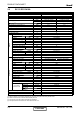
ELECTRICAL DATA 7. ELECTRICAL DATA 7.1 Single Phase Units MODEL SX 9 DCI SX 12 DCI SX 18 DCI SX 24 DCI SX 30 DCI To indoor To indoor To indoor To outdoor To outdoor Power Supply 1PH-230V50Hz 1PH-230V50Hz 1PH-230V50Hz 1PH-230V50Hz 1PH-230V50Hz Max Current, A 10 10 12 14 15 Inrush Current A 35 35 35 45 45 Starting Current A 10.5 10.5 10.5 10.5 10.5 Circuit Breaker A 16 16 20 20 20 Power Supply Wiring No.X Cross Section mm2 3 x 1.5 mm2 3 x 1.5 mm2 3 x 2.
B la c k Red B ro w n U V W W h it e P1 4 P4 1 2 P1 1 2 1 2 3 4 5 6 P16 P17 P18 P21 P22 P2 1 2 OAT P19 1 2 CONTENT Blue R ed Black L-F N-F COM NCOM L N COM E AR TH E AR TH FUSE Brown Red Y/G magnetic ring N/3 L/4 C/5 B lu e Brown Red Y/G POWE R SU PPL Y Blue Brown Red Y/G SX 9, 12, 18 DCI / GC 9, 12, 18 DCI EEV 8.1 Y/G P6 1 2 3 4 WIRING DIAGRAMS EMI f i l t er PCB 1 2 3 4 5 6 EARTH L N COM N-COM megatool P8 1 2 D i sp l ay 8.
WIRING DIAGRAMS 8.2 8-2 Indoor Unit: SX 24, 30 DCI CONTENT SM SX DCI 1-A.
WIRING DIAGRAMS 8.3 Outdoor Unit: GC 24, 30 DCI SM SX DCI 1-A.
REFRIGERATION DIAGRAMS 9. REFRIGERATION DIAGRAMS 9.1 SX 9, 12, 18, 24, 30 DCI Cooling Mode EEV Heating Mode EEV SM SX DCI 1-A.
TUBING CONNECTIONS 10. TUBING CONNECTIONS TUBE (Inch) ¼” ⅜” ½” ⅝” ¾” 11-13 13-20 11-13 40-45 13-20 11-13 60-65 18-25 11-13 70-75 18-25 11-13 80-85 40-50 11-13 TORQUE (Nm) Flare Nuts Valve Cap Service Port Cap 1. 2. 3. 4. 5. 6. 7. 8.
TROUBLESHOOTING 11. TROUBLESHOOTING WARNING!!! When Power Up – the whole outdoor unit controller, including the wiring, is under HIGH VOLTAGE!!! Never open the Outdoor unit before turning off the Power!!! When turned off, the system is still charged (400V)!!! It takes about 3 Min. to discharge the system. Touching the controller before discharging may cause an electrical shock!!! For safe handling of the controller please refer to section 11.6 below. 11.
TROUBLESHOOTING No SYMPTOM PROBABLE CAUSE CORRECTIVE ACTION 8 Compressor is on but outdoor fan does not work Problem with outdoor electronics or outdoor fan Check outdoor fan motor according to the procedure in section 11.5.3 , if not OK replace controller 9 Unit works in wrong mode (cool instead of heat or heat instead of cool) Electronics or power connection to RV Check RV power connections, if OK, Check RV operation with direct 230VAC power supply, if OK, Replace outdoor controller.
TROUBLESHOOTING When system enters diagnostics mode, only one fault code is shown. Order of priority is from the lower to the higher number. Diagnostics is continuously ON as long as power is ON. The current system operation mode will not be changed. If no fault occurred in the system, no fault code will be displayed during normal operation mode. The last fault code will be displayed even if the system has recovered from that fault.
TROUBLESHOOTING No Problem AO 5 4 3 2 1 28 Model A No 1 1 1 0 0 29 Model B No 1 1 1 0 1 30 Model C No 1 1 1 1 0 31 Model D No 1 1 1 1 1 * CN / LSN Units only 11.3.2 Indoor Unit Diagnostics and Corrective Actions No.
TROUBLESHOOTING No Problem AO 5 4 3 2 1 10 OMT is shorted (DCI72 / 72Z / 80) Yes 0 1 0 1 0 11 IPM Fault Yes 0 1 0 1 1 12 Bad EEPROM No 0 1 1 0 0 13 DC under voltage Yes 0 1 1 0 1 14 DC over voltage Yes 0 1 1 1 0 15 AC under voltage Yes 0 1 1 1 1 16 Mismatch IDU & ODU models (*SW 35V14 and above) Yes 1 0 0 0 0 17 No Communication Yes 1 0 0 0 1 18 Reserved No 1 0 0 1 0 20 Heat sink Over Heating No 1 0 1 0 0 21 Deicing N
TROUBLESHOOTING No. Fault 8 Compressor Lock 9 Bad Communication 11.4 Probable Cause Corrective Action Switch unit to STBY and restart If still not ok check compressor (11.5.4) If comp is ok replace OU controller If compressor is not ok replace compressor Communication quality is low reliability Check Indoor to Outdoor wiring and grounding Judgment by MegaTool MegaTool is a special tool to monitor the system states. Using MegaTool requires: • • • A computer with RS232C port.
TROUBLESHOOTING 11.5.4 Checking the Compressor. The compressor is brushless permanence magnetic DC motor. Three coil resistance is same. Check the resistance between three poles. The normal value should be below 0.5 ohm (TBD). 11.5.5 Checking the Reverse Valve (RV). Running in heating mode, check the voltage between two pins of reverse valve connector, normal voltage is 220VAC. 11.5.6 Checking the electrical expansion valve (EEV). The EEV has two parts, drive part and valve.
CONTROL SYSTEM 12. CONTROL SYSTEM 12.1 General Functions and Operating Rules The DCI software is fully parametric. All the model dependent parameters are shown in Blue color and with Italic style [parameter]. The parameters values are given in the last section of this control logic chapter of the service manual. 12.1.1 System Operation Concept The control function is divided between indoor and outdoor unit controllers.
CONTROL SYSTEM Target frequency limits as a function of outdoor air temperature (OAT): OAT Range Cooling Mode limits OAT < 6 Heating Mode limits No limit 6 ≤ OAT < 15 MaxFreqAsOAT1H MaxFreqAsOATC 15 ≤ OAT < 28 28≤ OAT MaxFreqAsOAT2H No limit 12.1.3.
CONTROL SYSTEM 12.1.5.2 Compressor starting control for DCI72/80 Step 1 Whenever the compressor starts up, after it has been off for more than 45 minutes, the compressor frequency cannot go below Step1RPS for 3 continuous minutes (this rule comes to ensure oil return to the compressor). Step 2 The compressor speed cannot go above Step2RPS once after each compressor start up for 3 continuous minutes (this rule comes to prevent oil exit from the compressor after its start up).
CONTROL SYSTEM OFAN Speed Compressor Target Frequency Routin A Routin B Routin C Routin D Freq=0 OFF OFF OFF OFF 10 ≤ Freq < OFLowFreq Low Low VL Low OFLowFreq ≤ Freq< OFMedFreq Medium Low VL Low OFMedFreq≤ Freq High Low Low Medium When compressor is switched to OFF and the heat sink temperature is above 55 degrees, the outdoor fan will remain ON in low speed for up to 3 minutes.
CONTROL SYSTEM 12.1.9.2 EEV Control for DCI72/72Z/80 The target EEV value is the sum of open loop value (OL) and a result of the accumulative correction values (CV).
CONTROL SYSTEM 12.3 Cool Mode NLOAD is calculated according to the difference between actual room temperature and user set point temperature by PI control. In high/ medium/ low indoor fan user setting, unit will operate fan in selected speed. In AutoFan user setting, fan speed will be adjusted automatically according to the calculated NLOAD. 12.4 Heat Mode NLOAD is calculated according to the difference between actual room temperature and user set point temperature by PI control.
CONTROL SYSTEM 12.6 Dry Mode As long as room temperature is higher then the set point, indoor fan will work in low speed and compressor will work between 0 and MaxNLOADIF1C Hz. When the room temperature is lower than the set point, compressor will be switched OFF and indoor fan will cycle 3 minutes OFF, 1 minute ON. 12.7 Protections There are 5 protection codes. Normal (Norm) – unit operate normally. Stop Rise (SR) – compressor frequency can not be raised but does not have to be decreased.
CONTROL SYSTEM 12.7.2.2 Indoor Coil Overheating Protection For 72/80 ICT Trend ICT <-2 -2 -1,0,1 2 >2 ICT >62 SC SC SC SC SC 60 ≤ ICT < 62 D1 D1 D2 D2 D2 58≤ ICT <60 SR SR D1 D2 D2 56≤ ICT < 58 SR SR SR D1 D2 54≤ ICT < 56 Norm Norm SR SR D1 52≤ ICT ≤ 54 Norm Norm Norm SR SR ICT <52 12.7.3 Norm Compressor Overheating Protection 12.7.3.
CONTROL SYSTEM 12.7.3.2 Compressor Overheating Protection for DCI72/80 CTT Trend CTT Fast Decreasing Decreasing No Change Increasing Fast Increasing CTT >105 100≤ CTT < 105 95≤CTT <100 SC SC SC SC SC D1 D1 D2 D2 D2 SR SR D1 D2 D2 93≤CTT < 100 85≤CTT < 95 SR SR SR D1 D1 90≤CTT ≤ 93 80≤CTT ≤ 85 Norm Norm Norm SR SR CTT <90 CTT <80 Cool Heat CTT >105 100≤ CTT < 105 98≤CTT <100 12.7.
CONTROL SYSTEM 12.7.5.2 Heat Sink Overheating Protection For DCI72/80 Delta HST HST <-2 -2 -1,0,1 2 >2 HST≥ 81 SC SC SC SC SC 79 ≤ HST < 81 D1 D1 D2 D2 D2 75 ≤ HST < 79 SR SR D1 D2 D2 73≤ HST< 75 SR SR SR D1 D1 71 ≤ HST ≤ 73 Norm Norm Norm SR SR HST < 71 12.7.
CONTROL SYSTEM Deicing Operation Procedure ► OCT 12 0 T h re s h o ld COMP ON T1 T2 DT m a x. 1 2 m in u te s D e ic e F re q C h R V RV HEAT COOL O FAN T1 T3 T3 ON OFF EEV E E V D e ic e rO p e n Any T1=60 secondes;T2=36 secondes;T3=6 secondes 12.7.7.2 Outdoor coil Deicing Protection For DCI72/80 Entering Deicing Conditions Deicing operation will start when either one of the following conditions exist: Case 1: OCT < OAT – 8 AND TLD > DI Case 2: OCT < OAT – 12 AND TLD > 30 minutes.
CONTROL SYSTEM Deicing Operation Procedure ► OCT 12 0 Threshold COMP ON T1 T2 T1 max. 12 minutes DT HEAT RV T3 COOL OFAN T3 ON OFF EEVDeicerOpen EEV Any T1=50 secondes;T2=36 secondes;T3=6 secondes 12.7.
CONTROL SYSTEM Overflow when unit is ON Overflow Water Level Overflow when unit is OFF Normal ON OPER LED OFF BLINK ANY NLOAD NLOAD is forced to 0 0 ON PUMP OFF 8 min 12.8 8 min 8 min Indoor Unit Dry Contact Indoor unit Dry contact has two alternative functions that are selected by J9. Function Contact=open Contact=short J9=open Presence Detector Connection No limit Force to STBY J9=short Power Shedding Function No limit Limit NLOAD 12.
CONTROL SYSTEM 12.10 On Unit Controls and Indicators 12.10.1 Indoor Unit controller Controls and Indicatiors for All Models Except for Floor/Ceiling model During OFF, Fan, Cool, Heat, Dry, and Auto modes (for operation in other modes, see at the relevant spec paragraph): STAND BY INDICATOR 1. Lights up when the Air Conditioner is connected to power and ready to receive the R/C commands OPERATION INDICATOR 1. Lights up during operation. 2. Blinks for 300 msec.
CONTROL SYSTEM 12.11 Test Mode 12.11.1 Entering Test Mode System can enter Test mode in two ways: Automatically when the following conditions exists for 30 minutes continuously: Mode = Cool, Set point = 16, Room temperature = 27(+1/−2), Outdoor temperature = 35(+2/-1) Or Mode = Heat, Set point = 30, Room temperature = 20±1, Outdoor temperature = 7±(+1/-2) Manually when entering diagnostics with the following settings: Mode = Cool, Set point = 16 Mode = Heat, Set point = 30 12.11.
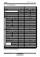
CONTROL SYSTEM Model dependent parameters - DNG Unit A (DNG50) B (DNG60) C (DNG72) D (DNG80) 3 62 74 22 28 30 32 40 50 63 120 127 127 20 127 127 127 127 127 127 127 27 62 74 3 77 80 22 28 30 32 40 50 63 120 127 127 20 127 127 127 127 127 127 127 27 77 80 4 57 55 22 28 30 32 40 63 85 115 127 127 20 127 127 127 127 127 127 127 27 57 55 4 60 63 22 28 30 32 40 78 100 127 127 127 20 127 127 127 127 127 127 127 27 60 63 Cap .
CONTROL SYSTEM Model dependent parameters - SX A (SX 18) B (SX 24) C (SX 30) Cap .
CONTROL SYSTEM 12.12.
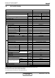
CONTROL SYSTEM Model dependent parameters for DCI72Z No. Name Single DCI-72Z 1 MinFreqC 15 2 MaxFreqC 70 3 MinFreqH 15 4 MaxFreqH 90 7 Step1Freq 35 8 Step2Freq 55 9 Step3Freq 90 10 OFMinRPM 8 11 OFMaxRPM 90 12 NightRPM 65 13 OFNNoiseMaxRPM 78 14 CTTOH1 90 15 CTTOH2 95 16 CTTOH3 100 17 CTTOH4 105 18 CCROC1 12.5 19 CCROC2 13.3 20 CCROC3 14.1 21 CCROC4 14.
CONTROL SYSTEM Model dependent parameters for DCI72/80 Compressor Parameters Value MinOFFTime 3 MinOnTime 3 MaxCTT1 90 MaxCTT2 90 MinSpeedAsCTT1 26 MinSpeedAsCTT2 26 MaxSpeedC 75 MaxSpeedH 95 Step1RPS 40 Step2RPS 60 Step3RPS 75 NormAcc (sec/RPS) 1 NormDec (sec/RPS) 1 Down1(Sec/RPS) 12 Down2 (Sec/RPS) 7 DeiceAcc (Sec/RPS) 0.2 DeiceDec (Sec/RPS) 0.
EXPLODED VIEWS AND SPARE PARTS LISTS 13. EXPLODED VIEWS AND SPARE PARTS LISTS 13.1 Indoor Unit: SX 9, 12 DCI SM SX DCI 1-A.
EXPLODED VIEWS AND SPARE PARTS LISTS 13.2 Indoor Unit: SX 9, 12 DCI No Part No Description 1 2 3 4 5 6 7 8 9 10 11 12 13 14 15 16 17 18 19 307979 382334 452731900 373247 455000600 323425 293321 452987400 4520158 4521029 372341 373245 221555 307981 484001 4525333 373244 371257 370281 375209-01 375209-05 375209-16 375209-17 4521827 4521831 372338 372339 263034 436665 391508 234213 391725 4521070 438413 438082 452935900 311036 Back panel Base panel EPS Evap.
EXPLODED VIEWS AND SPARE PARTS LISTS 13.3 Indoor Unit: SX 18, 24, 30 DCI SM SX DCI 1-A.
EXPLODED VIEWS AND SPARE PARTS LISTS 13.4 Indoor Unit: SX 18 DCI No Part No Description 1 307980 Back panel 1 2 382333 Base panel EPS 1 3 4527244 Evap.
EXPLODED VIEWS AND SPARE PARTS LISTS 13.5 Indoor Unit: SX 24, 30 DCI No. Part No. Description Qty 1 484002 Grille 1 2 221554 Air Filter 2 3 373244 Right panel 1 4 307982 Frame Asy 1 5 371071-72 Display panel 1 6 470680004 Evaporator Assy 1 7 370280 Air Outlet Assy 1 8 285032 Draining Hose 1 9 372336 Horizontal louver front 1 9 372337 Horizontal louver back 1 10 371255 Vert.
EXPLODED VIEWS AND SPARE PARTS LISTS 20 21 22 23 24 25 26 27 29 28 30 40 13-6 42 41 38 37 36 35 1 2 3 4 34 5 6 7 8 9 33 32 39 Outdoor Unit: GC 9, 12 DCI 31 13.6 CONTENT SM SX DCI 1-A.
EXPLODED VIEWS AND SPARE PARTS LISTS 13.7 Outdoor Unit: GC 9, 12 DCI No. 1 2 3 4 5 6 7 8 9 10 11 12 13 14 15 16 17 18 19 20 21 22 23 24 25 26 27 28 29 30 31 32 33 34 35 36 37 38 39 40 41 42 Part No.
EXPLODED VIEWS AND SPARE PARTS LISTS 13.8 13-8 Outdoor Unit: GC 18 DCI CONTENT SM SX DCI 1-A.
EXPLODED VIEWS AND SPARE PARTS LISTS 13.9 Outdoor Unit: GC 18 DCI No. 1 2 3 4 5 6 7 8 9 10 11 12 13 14 15 16 17 18 19 20 21 22 23 24 25 26 27 28 29 30 31 32 33 34 35 36 37 38 39 40 41 42 Part No.
EXPLODED VIEWS AND SPARE PARTS LISTS 13.10 13-10 Outdoor Unit: GC 24, 30 DCI CONTENT SM SX DCI 1-A.
EXPLODED VIEWS AND SPARE PARTS LISTS 13.11 Outdoor Unit: GC 24, 30 DCI No. Part No.
APPENDIX A APPENDIX A INSTALLATION AND OPERATION MANUAL ► OPERATION MANUAL SX 9, 12, 18, 24, 30 DCI ► INSTALLATION MANUAL SX 9, 12, 18, 24, 30 DCI SM SX DCI 1-A.