SERVICE MANUAL YUDA060 / CAD060 Outdoor unit YUDA060 Indoor unit CAD060
>_]]VbTZR\ _^UZdZ_^Vb CONTENTS Contents……………………………………………………….....2 1. Description of products & features………………………….3 2. Specification…………………………………………………...5 3. Dimensions…………………………………………………....7 4. Pipe and wiring installation…..……………………………....9 5. PCB photo, wiring diagram and function description……..32 6. Diagnostic code and troubleshooting.……………………... 47 7. Outdoor performance curves………..……………………....52 8. Indoor air velocity and temperature distribution curves......53 9.
.9773:1506 -5: .9825;5983: 1.Description of products & features 1.1.
Commercial Air Conditioner 1.4 Product features By integrating intelligential technology of Airwell Residential, with universal indoor and outdoor units, make more intelligent and flexible choices on purchasing, easier inventory management to every customer. Good for choice Multi-choice of capacity and appearance of indoor unit according to various rooms.
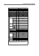
Item M YUDA060 Power cable H07RN-F 5G 4.0mm2 Communication cable / Connecting cable H05RN-F 4G 0.75mm2 Power source 3N~,380∼400, 50Hz N, V, Hz Unit model (color) YUDA060(WHITE) LNB42FUAMC(MITSUBISHI ELECTRIC COMPRESSOR CO.,LTD) Model / Manufacture/place Compressor OIL model FV50S Oil charging 1400CM3 Type Rotary Type × Number axial×2 r/min 930±40 kW 0.80×2 Fan motor output power kW 0.150×2 Air-flow(H-M-L) m³/h 6500 Type / Diameter mm TP2M/Φ7.
>_]]VbTZR\ _^UZdZ_^Vb Item Function Capacity Sensible heat ratio Total power input Max. power input EER or COP M kW kW W W/W Dehumidifying capacity Power cable Power source Running /Max.Running current Start Current Circuit breaker CAD060(AIRWELL) cooling heating 14.0(4.0~15.5) 15.0(4.0~17.5) 0.73 4.4(2.0----6.5) 4.36(2.0---6.5) 6500 3.21(A) 10‐³×m³/h 5.0 N, V, Hz A/A A A / 1, 220~230, 50 7.3(2.9-10.5)/10.5 7.3(2.9-10.5)/10.5 / 3.
>_]]VbTZR\ _^UZdZ_^Vb 3.
>_]]VbTZR\ _^UZdZ_^Vb CAD060 ov er ov er ov er ov er 780 (hanging position) 860 - 890 (ceiling hole) 8 1250~1280 (ceiling hole) 1070 (hanging position) over 1000
>_]]VbTZR\ _^UZdZ_^Vb 4. Outdoor Unit Installation Safety Precautions Carefully read the following information in order to operate the air conditioner correctly. Below are listed three kinds of Safety Precautions and Suggestions. WARNING Incorrect operations may result in severe consequences of death or serious injuries. CAUTION Incorrect operations may result in injuries or machine damages; in some cases may cause serious consequences.
>_]]VbTZR\ _^UZdZ_^Vb WARNING Have the unit professionally installed. Improper installation by an unqualified person may result in water leak, electric shock, or fire. Place the unit on a stable, level surface that withstands the weight of the unit to prevent the unit from tipping over or falling causing injury as a result. Only use specified cables for wiring. Securely connect each cable, and make sure that the cables are not straining the terminals.
>_]]VbTZR\ _^UZdZ_^Vb Precautions for Handling Units for Use with R410A Caution Do not use the existing refrigerant piping Use a vacuum pump with a reverse-flow check valve. If other types of valves are used, the vacuum pump oil will The old refrigerant and refrigerator oil in the existing piping flow back into the refrigerant cycle and cause the refrigerator contain a large amount of chlorine, which will cause the oil to deteriorate. refrigerator oil in the new unit to deteriorate.
>_]]VbTZR\ _^UZdZ_^Vb Before Installing (Relocating) the Unit or Performing Electric Caution Ground the unit. Do not connect the grounding on the unit to gas pipes,water pipes, lightning rods, or the grounding terminals of telephones. Improper grounding presents a risk of electric shock, smoke, fire, or the noise caused by improper grounding may cause the unit to malfunction. Do not spray water on the air conditioners or immerse the air conditioners in water.
>_]]VbTZR\ _^UZdZ_^Vb Read Before Installation Items to Be Checked (1). Verify the type of refrigerant used by the unit to be serviced. Refrigerant Type: R410A (2). Check the symptom exhibited by the unit to be serviced. Look in this service handbook for symptoms relating to the refrigerant cycle. (3). Be sure to carefully read the safety precautions at the beginning of this document. (4).
>_]]VbTZR\ _^UZdZ_^Vb Piping Materials Types of Copper Pipes (Reference) Maximum Operation Pressure Applicable Refrigerants 3.4MPa R22, R407C 4.15MPa R410A Use pipes that meet the local standards. Piping Materials/Radial Thickness Use pipes made of phosphorus deoxidized copper. Since the operation pressure of the units that use R410A is higher than that of the units for use with R22, use pipes with at least the radial thickness specified in the chart below. (Pipes with a radial thickness of 0.
>_]]VbTZR\ _^UZdZ_^Vb Air Tightness Test No changes from the conventional method. Note that a refrigerant leakage detector for R22 or R407C cannot detect R410A leakage. NO NO Halide torch R22 or R407C leakage detector Items to be strictly observed : 1.Pressurize the equipment with nitrogen up to the design pressure and then judge the equipment's air tightness, taking temperature variations into account. 2.When investigating leakage locations using a refrigerant, be sure to use R410A. 3.
>_]]VbTZR\ _^UZdZ_^Vb Name of Parts YUDA060 Air inlet Air outlet Compressor (Inside of unit) 16
>_]]VbTZR\ _^UZdZ_^Vb Installation of Outdoor Unit 1. Selection of the place of installation Select the place of installation satisfying the following conditions and, at the same time, obtain a consent from the client or user. Place where air circulates. Place free from heat radiation from other heat sources. Place where drain water may be discharged. Place where noise and hot air may not disturb the neighborhood. Place where there is not heavy snowfall in the winter time.
>_]]VbTZR\ _^UZdZ_^Vb 3.
>_]]VbTZR\ _^UZdZ_^Vb Piping Connection 1. Piping diagram YUDA060 Flare connection Gas pipe Indoor unit 3-way stop valve Outdoor unit Liquid pipe 3-way stop valve 2. Piping size 90+0.5 YUDA060 Liquid pipe 9.52x0.8mm Gas pipe 19.05x1.0mm Install the removed flare nuts to the pipes to be connected, then flare the pipes. 3.
>_]]VbTZR\ _^UZdZ_^Vb Air Tightness Test After finishing connection of refrigerant pipe, it shall perform air tightness test. The air tightness test adopts nitrogen tank to give pressure according to the pipe connection mode as the following figure shown. The gas and liquid valve are all in close state. In order to prevent the nitrogen entering the circulation system of outdoor unit, tighten the valve rod before giving pressure (both gas and liquid valve rods).
>_]]VbTZR\ _^UZdZ_^Vb Vacuuming Piping vavuum method: to use vacuum pump Liquid stop valve Gas stop valve 1. Detach the service port's cap of gas stop valve, the valve rod's cap for liquid stop valve and gas stop valve, and connect the service port into the projection of charge hose (low) for gaugemanifold. Then connect the projection of charge hose (center) for gaugemanifold into vacuum pump. Gauge manifold(R410A) Vacuum pump(R410A) 2.
>_]]VbTZR\ _^UZdZ_^Vb Electrical Wiring WARNING! DANGER OF BODILY INJURY OR DEATH TURN OFF ELECTRIC POWER AT CIRCUIT BREAKER OR POWER SOURCE BEFORE MAKING ANY ELECTRIC CONNECTIONS. GROUND CONNECTIONS MUST BE COMPLETED BEFORE MAKING LINE VOLTAGE CONNECTIONS. Precautions for Electrical wiring Electrical wiring work should be conducted only by authorized personnel. Do not connect more than three wires to the terminal block.
>_]]VbTZR\ _^UZdZ_^Vb Wiring procedure 1) Remove set screws on the side before taking off the front panel toward the direction. 2) Connect wires to the terminal block correctly and fix the wires with a wire clamp equipped nearby the terminal block. 3) Route the wires in a proper way and penetrate the wires through the opening for electrical wiring on the side panel. WARNING: INTERCONNECTING WIRES MUST BE WIRED ACCORDING TO FIGURE BELOW. INCORRECT WIRING MAY CAUSE EQUIPMENT DAMAGE.
Installation 5. Installation CAUTIONS: To ensure proper installation, read "Cautions" carefully before working. After installation, start the unit correctly and show customers how to operate and maintain the unit. Meanings of Warning and Cautions: Warning! Serious injury or even death might happen, if it is not observed. Caution! Injury to people of damages to machine might happen, if it is not observed. WARNING! Installation shall be done by professional people, don't install unit by yourself.
Installation Before installation Determine the way to carry unit to installation place. Don't remove packing until unit reaches installation place. If unpacking is unkavoidable, protect unit properly. Selection of installation place (1) Installation place shall meet the following and agreed by customers: Place where proper air flow can be ensured. No block to air flow. Water drainage is smpoth. Place strong enough to support unit weight.
Installation Installation of indoor unit In the case of new ceiling (1) Install unit temporally Put suspending bracket on the suspending bolt. Be sure to use nut and washer at both ends of the bracket. (2) As for the dimensions of ceiling hole, see paper pattern. Ask your real estate dealer for details. Center of the hole is marked on the paper pattern. Center of the unit is marked on the card in the unit and on the paper pattern. Mount paper pattern 5 onto unit using 3 screws 6 .
Installation Refrigerant piping (As for outdoor piping, please refer to installation of outdoor unit) Outdoor is precharged with refrigerant. Be sure to see the Fig.1, when connecting and removing piping from unit. For the size of the flare nut, please refer to Table 1. Apply refrigerant oil at both inside and outsid of lflare nut. Tighten it band tight 3-4 turns then tighten it. Use torque specified in Table 1. (Too much force may damage flare nut, causing gas leakage).
Installation (2) Check if water drainage is smooth after installation. Charge, through air outlet or inspecting hole, 1200ccd water to see water drainage. After wiring Check water drainage in cooling operation. When wiring is not complete Remove cover of control box, connect 1PH power to terminal 1 and 2 on terminal block, use remote controller to operate the unit. Note, in this operation, fan will be running. Upon confirmation of a smooth water drainage, be sure to cut off power supply.
Installation Terminal block Cover of control box(2) Don't fail to seal it, or water may come in. Grounding lead Rubber tube A Cover of control box(1) Rubber Note: Have it sealed, leaving no space. tube Seal pad (small size 12 ) (Wind around wire) In Out <> Attach seal pad Field wiring Connect wires of the Don't connect wires of Don't connect wires Obscrve the following when connecting power supply same specifications the same specifications of the different specifications. at two sides.
Installation Part a of the pad Swing flap motor Fig. 5 Side of ornament panel (3)Wiring on ornament panel Connecting of wiring of the swing flap motor on ornament panel. (2 places) (Refer to Fit . 10) If connecting is not made, error code (A7) appears on remote controller. So, make proper connecting. Side of indoor unit Fig. 10 Wiring diagram 3. Install ornament panel on indoor unit. Hook (1) As shown in Fig.
Installation (2) Install cover plate on the corner 1 As shown in Fig. 11 tie the 2 cover plate onto the bolt on ornament plate. Install cover plate onto ornament plate. (Refer to Fig. 12) Slide all five hold rings to let them drop in holes Fig. 11 on ornament plate, Fig. 12 Pay special care to the following and check after installation Item to the checked Unproper installation may cause Check Is indoor unit firmly installed? Unit might fall down, make vibration or noise.
>_]]VbTZR\ _^UZdZ_^Vb 5. PCB photo,Wiring diagram and function description 5.1 Outdoor unit 5.1. 1.
DC FAN MOTOR 33 N capacitor L M H CN14 M ON SW1-4 ON SW1-5 ON SW1-5 SIGNLE FAN DOUBLE FAN NOTE: 1.DESHAED FRAMES ARE OPTIONAL, AND IN SOME MODELS ARE NOT AVAILABLE. 2.USER SHOULD NOT TO CHANGE THE DIP SWITCH SW1,SW6.
>_]]VbTZR\ _^UZdZ_^Vb 3. Main control functions 3.
>_]]VbTZR\ _^UZdZ_^Vb 3.2 Outdoor frequency control 3.2.1 Compressor running frequency range: 30-91RPS. 3.3 Electronic expansion valve (EEV) control: 3.3.1 Electronic characteristic: Max. open angle 500 Pulse Driving speed PPS 3.3.2 Initialization of EEV EEV driving speed: open direction: 32MS; close direction: 32MS 3.3.3 Open angle limit of EEV Unit stop Adjustable upper limit Cool/dry 250(E) 480(E) heat 250(E) 480(E) 3.3.
>_]]VbTZR\ _^UZdZ_^Vb exchanger and make defrosting control. 3.5.1 Enter condition: After the unit is in heating for 10 minutes and compressor run for 45 minutes in all , according to check the defrosting temp. sensor Te and outdoor ambient temp. sensor Tao, if they can meet the following condition, entering in defrosting operation. 1、 5℃(E)
>_]]VbTZR\ _^UZdZ_^Vb 3.6 Frequency control when Td is too high Purpose : make compressor frequency control if the discharging temp. is too high, to low the discharging temp. efficiency and ensure the system can run normally. If keeps for 10s, the unit stops. 3 minutes later, the Discharging temp. Td unit can re-startup.
>_]]VbTZR\ _^UZdZ_^Vb 3.8.2 Procedure Cooling mode: refer to “the oil return procedure in cooling mode” Heating mode: refer to “the oil return procedure in heating mode” 3.8.3 The protection treatment in oil return operation: In the course of cooling oil return, because of all kinds of protection or abnormal unit stop, after the unit restart, the time will not be cleared, the system need another oil return operation.
>_]]VbTZR\ _^UZdZ_^Vb Send oil return signal Inverter compressor indicated FQY 60s oil return beginning oil return over oil return frequency 120s Soft startup 0HZ 0HZ 5s outdoor motor auto auto auto(TC control) 4-way valve ON OFF 15s 450pulse 450 pulse 300pulse(E) PMV auto open angel auto open angle all indoor motor ON OFF anti-freeze startup Quit condition of oil return OR Max.
>_]]VbTZR\ _^UZdZ_^Vb 5.2 Indoor unit 5.2.
Y/G S T POWER SUPPLY R R B BL W R TD TS TC CN17 TO INDOOR UNIT N 1 2 3 Y/G CN4 S L3 FUSE CN16 L2 L1 T6.3A/250VAC N CN6 CN3 CN2 CN7 LP TA CN5 HP CT1 NO OFF CT2 transformer CN12 1234 5678 CN13 CN14 CN10 CN11 OR CIRCUIT DIAGRAM OF OUTDOOR UNIT R W B M capacity W:WHITE B:BLACK R:RED BL:BLUE Y/G:YELLOW/GREEN crankcase heater compressor R(U) Y/G S(V) T(W) R ac contactor W B 4-way vavle M M capacity 0150509028 >_]]VbTZR\ _^UZdZ_^Vb 5.2.2.
>_]]VbTZR\ _^UZdZ_^Vb 2. Sign definition: Indoor Tai Ambient temp. outdoor Tc1 Tc2 Tm Outlet Inlet mid pipe pipe coil temp. temp. temp. Tcomp1,2 Temp. compensation Tao Ambient temp. Toci Tc Thick pipe mid of heat condenser exchanger temp. Te Defrost temp. Ts Td Compressor Compressor suction discharging temp. temp. Tset Set temp. 3. Dry operation Tai<16℃, indoor unit stops running and sends stop-unit signal to outdoor.
>_]]VbTZR\ _^UZdZ_^Vb 6.4 In AUTO mode, when the indoor unit occurs abnormal operation, the indoor unit will keep OFF state, and the buzzer will not sound until the outdoor mode and the requested mode of indoor unit are the same. 6.5 COOL (included AUTO COOL), DRY, FAN are not abnormal mode. 6.6 HEAT and FAN are not abnormal mode. 7. Control for discontinuous operation After the unit starts up in cooling/heating mode, in 5 minutes, the compressor run/stop will not be controlled by the room temp.
>_]]VbTZR\ _^UZdZ_^Vb 12. Water pump control 12.1 Water pump will be electrified when indoor unit enters non-heating mode until indoor unit stops. 5 minutes later after indoor unit stops, water pump will stop. 12.2 When indoor unit is in heating mode, water pump will not operate. 12.
>_]]VbTZR\ _^UZdZ_^Vb 17. Healthy negative ion function When receiving the healthy signal from the wired controller or remote controller, if fan motor is running, the negative ion will work; If the fan motor stops, the negative ion generator will stop. 18. Auto-restart function 18.1 Wired control type: jumper J07 at high level, auto-restart is available, if at low level, auto-restart is cancelled; when out of factory, the unit is with auto-restart function. 18.
>_]]VbTZR\ _^UZdZ_^Vb 20. Setting method of temperature compensation Tcomp A. Wired control type unit: this function is not available B. Remote control type unit: In cooling or heating mode, there is always with the temp. compensation. In heating mode: In 24℃ heating mode, press SLEEP(or SWING) button 7 times continuously within 5 seconds, indoor buzzer sounds twice, that shows temp. compensation works. Switch on the unit in heating mode by the remote controller, press TEMP button to set the set temp.
>_]]VbTZR\ _^UZdZ_^Vb 6. Diagnostic code and trouble shooting 6.1.1.
>_]]VbTZR\ _^UZdZ_^Vb 6.1.2.
>_]]VbTZR\ _^UZdZ_^Vb 6.2.
>_]]VbTZR\ _^UZdZ_^Vb Trouble 3: Communication failure between indoor and outdoor start as per the wiring diagram, check if communication wiring is correct no re-wiring, and check again yes check if the communication port connecting to the indoor/outdoor PCB is in open circuit no if the power cable and the communication wire are too close, resulting in the wrong commission data no PCB is faulty, replace and check again yes yes adjust the distance and check again replace the communication co
>_]]VbTZR\ _^UZdZ_^Vb Trouble 7: AC current over current protection or current transducer damaged, or compressor blocked rotor, compressor great vibration, compressor abnormal startup, state detecting curcuit abnormal or compressor damaged. The former twice failure can be resumed automatically, if outdoor board occurs this failure always, and can not be resumed for a long time, that shows: 1.
>_]]VbTZR\ _^UZdZ_^Vb 7. Outdoor performance curves YUDA060 cooling capacity curves 19000 ‐6/‐7 heating capacity ‐6/‐7 power input ‐4/‐5 heating capacity ‐4/‐5 power input ‐1/‐2 heating capacity ‐1/‐2 power input 1/0 heating capacity 1/0 power input 18000 17000 16000 15000 14000 13000 12000 11000 10000 9000 6/5 heating capacity 6/5 power input 8000 7000 6000 7/6 heating capacity 7/6 power input 5000 4000 3000 2000 1000 0 16/10 18/12 20/14.
$LU 9HORFLW\ 'LVWULEXWLRQ 8. Indoor air velocity and temperature distribution curves 8.
>_]]VbTZR\ _^UZdZ_^Vb 9. Noise level a. Casset type indoor unit .7/ V`nodib dggpnom\o`@ .
58 54 50 46 42 38 34 30 26 22 18 14 third octave band frequency Hz noise level-CAD060 sound pressure level DB cooling high 55 fan low fan med fan high heating high heating med heating low cooling low cooling med >_]]VbTZR\ _^UZdZ_^Vb
>_]]VbTZR\ _^UZdZ_^Vb .7/ Wbpqfkd fiirpqo^qflk@ 7j .8/ Wbpqfkd `lkafqflk@ ^4 Xkfq orkkfkd fk qeb kljfk^i `lkafqflk _4 Wbpq fk qeb pbjf3^kb`elf` `e^j_bo `4 Qlfpb ibsbi s^ofbp colj qeb ^`qr^i c^`qlop pr`e ^p ollj pqor`qrob2 bq`4 .9/ Test method 1. Set the unit: 1) the unit is placed on the rubber whose thickness is 5mm; 2) if the height between the air outlet and ground is less than 1m, block the unit up to 1m.far from ground 2.
78 74 70 66 62 58 54 50 46 42 38 34 30 26 22 18 14 10 6 2 third octave band frequency Hz noise level-YUDA060 heating high cooling high >_]]VbTZR\ _^UZdZ_^Vb 57 sound pressure level DB
>_]]VbTZR\ _^UZdZ_^Vb 10. Sensor characteristic 1.
>_]]VbTZR\ _^UZdZ_^Vb 59
>_]]VbTZR\ _^UZdZ_^Vb R25=23KΩ±3% B25/50=4200K±3% T(℃) -20℃ -19℃ -18℃ -17℃ -16℃ -15℃ -14℃ -13℃ -12℃ -11℃ -10℃ -9℃ -8℃ -7℃ -6℃ -5℃ -4℃ -3℃ -2℃ -1℃ 0℃ 1℃ 2℃ 3℃ 4℃ 5℃ 6℃ 7℃ 8℃ 9℃ 10℃ 11℃ 12℃ 13℃ 14℃ 15℃ 16℃ 17℃ 18℃ 19℃ 20℃ 21℃ 22℃ 23℃ Rnom(KΩ 266.905 250.866 235.895 221.911 208.838 196.609 185.163 174.443 164.399 154.983 146.153 137 87 137.87 130.096 122.799 115.946 109.51 103.462 97.779 92.437 87.415 82.691 78.248 74.067 70.133 66 43 66.43 62.943 59.659 56.566 53.651 50.904 48.314 45.872 43.569 41.
>_]]VbTZR\ _^UZdZ_^Vb 24℃ 25℃ 26℃ 27℃ 28℃ 29℃ 30℃ 24.111 23 21.947 20.949 20.003 19.104 18.252 75℃ 76℃ 77℃ 78℃ 79℃ 80℃ 81℃ 61 2.997 2 895 2.895 2.798 2.704 2.614 2.528 2.
>_]]VbTZR\ _^UZdZ_^Vb 11.
>_]]VbTZR\ _^UZdZ_^Vb 63
>_]]VbTZR\ _^UZdZ_^Vb wIWXb \^ST[ WPb ]^c cWXb Ud]RcX^]|x 64
>_]]VbTZR\ _^UZdZ_^Vb Wired controller Fan speed switch Change wind speed Mode switch Choose running mode Swing switch Open and close air flap Health switch Used to control oxygen function and negative ion TEMP switch Used for changing set temperature MODE MODE AUTO FAN ONLY COOL DRY FAN AUTO HIGH MED LOW CENTRAL OPERATION STANDBY PRE-HEAT DEFROST HEAT FIX FILTER HEALTH CHECK SWING UNIT NO. DEMAND TES CEN. ADD. SYS. ADD.
>_]]VbTZR\ _^UZdZ_^Vb ON/OFF operation 2 MODE MODE FAN OPERATION HIGH 4 The line controller displays the running state in the latest time (timing and swing state may not be displayed). 5 1. Press "ON/OFF" switch. The air conditioner starts operating, and the light on the wired controller is on. SWING FAN HEALTH TEMP CLOCK TIME COOL C ROOM TEMP. TIMER SET 3 RECOVERY FILTER RESET 1 ON/OFF 2.Choose operation mode.
>_]]VbTZR\ _^UZdZ_^Vb Present time setting The timing is based on the real time. Thus, the real time should be regulated in advance. The clock regulation steps are as follows: 1.Press "CLOCK" switch MODE MODE FAN SWING "CLOCK" flickers, and the time displayed is the real time. FAN OPERATION HIGH TEMP HEALTH 2.Press " C ROOM TEMP. TIME TIMER SET CHECK FILTER " to regulate the time. The time increases a minute each time you press " " switch.
>_]]VbTZR\ _^UZdZ_^Vb Timing setting OFF timing: when a set time has elapsed, the unit stops running. ON timing: when a set time has elapsed, the unit starts. MODE MODE FAN SWING FAN HIGH OPERATION TEMP HEALTH 1.Press "TIME" switch. COOL CLOCK C ROOM TEMP. The display changes with the following sequence: on on no display CYCLE ON OFF OFF OFF TIME TIMER SET CHECK FILTER RECOVERY TIMER ON Press "ON/OFF"switch firstly, and set up operation mode.
>_]]VbTZR\ _^UZdZ_^Vb Query indoor malfunction history: In the state of power on or power off, press [CHECK] button, enter the malfunction-querying mode of all indoor units in the group. Then [CHECK] and [UNIT NO.] will display, and the actual indoor numbers will be displayed in some sequence (unit number is in decimals).
>_]]VbTZR\ _^UZdZ_^Vb Installation Manual For Wire Controller 1. Take down wire controller from the holder MODE CENTRAL OPERATION STANDBY PRE-HEAT DEFROST FIX CHECK DEMAND SWING C F SYS. ADD. SWING Wire controller 52¡ 0.2 TEMP HEALTH FILTER TES HEALTH UNIT NO. CEN. ADD. FAN CLOCK TIME MANUAL ROOM TEMP. SET TEMP. TIMER SET CHECK FILTER RECOVERY TIMER CLOCK UP DOWN VENTILATION ON AUTO OFF RECOVERY DAILY NORMAL Bracket RESET 5.3 HEAT FAN AUTO HIGH MED LOW 10.