
Service manual
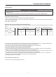
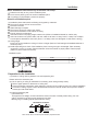


(2) Check if water drainage is smooth after installation.
Charge, through air outlet or inspecting hole, 1200ccd water to see water drainage.
After wiring
controller to operate the unit.
Note, in this operation, fan will be running.
Upon confirmation of a smooth water drainage, be sure to cut of
f power supply.
Check water drainage in cooling operation.
When wiring is not complete
Remove cover of control box, connect 1PH power to terminal 1 and 2 on terminal block, use
remote
Installation
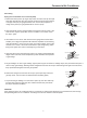
Method of water charging
Charge water from
air outlet
Charge water from
inspecting hole
Watering can of plastic
pipe should be about
100 mm long
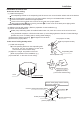
100mm
Water drainage port for
maintenance
(Drain water from
this hole)
Self-provided stiff pipe
Maintenance
Inspecting hole
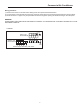
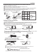
1 2 3 D
OUTDOOR UNIT
TERMINAL BLOCK
INDOOR UNIT
TERMINAL BLOCK
POWER SUPPLY:
380-400V,3N~,50Hz
R ST
N 1 2 3
1 2 3
Y/G
Y/G
Wiring
All supplied parts. materials and wiring operation must in appliance with
local code and regulations.
Use copper wire only.
When make wiring, please refer to wiring diagram also.
All wiring work must be done by qualified electricians.
A circuit breaker must be installed, which can cut power supply to all system.
See Installation Manual of outdoor unit for specifications of wires, circuit breaker, switches and wiring etc.
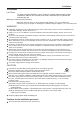
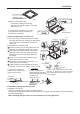
Connecting of unit
Remove cover of switch box (1) , drag wires into rubber tube A, then, after proper wiring with other wires,
tighten clamp A. Connect wires of correct pole to the terminal block inside.
Wind seal
12 around wires. (Be sure to do that, or, dew may occur).
Upon connecting, replace control box cover (1) and (2).
Cover of controll box
PCB on
indoor unit
Terminal block
Connect with
outdoor unit
Terminal block
28