
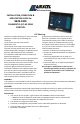
Application Guide


2
INSTALLATION
OEM supplies the RJ45 cable that connects the thermostat, control boxes and MAXXFans.
MAXXFans require their own 12Vdc for 12Vdc fan functions. 12Vdc control voltage can be provided at either
the control box or the thermostat and will be carried to the other components via the RJ45 cable.
The thermostat comes with a mounting plate.
Furnace wire is now at the control box.
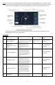
Thermostat and Room Temperature Sensor Location
This system is designed to work one of two ways.
• A built-in sensor on the thermostat can control Zone 1. In this case, the thermostat must be installed in
Zone 1.
• Alternatively, a remote temperature sensor can be connected to Zone 1. This situation would allow the
thermostat to be located virtually anywhere in the coach, as long as the user can get to the thermostat
to operate it. Every zone other than Zone 1 must always have a remote temperature sensor to control
the system. The Remote Room Sensor available is 8330-3091 (white) and 8330-3101 (black).
This thermostat is a sensitive instrument. For accurate temperature control and comfort the following
considerations should be considered when locating the remote sensors and the thermostat if the
thermostat is to be used as the Zone 1 temperature sensor.
1. Locate on an inside wall about five feet above the floor. Pick a dry area where air circulation is good, but
not in line with exterior doors.
2. Do not install where there are unusual heating conditions, such as direct sunlight, heat producing
appliances (television, radio, wall lamps, etc.), or a furnace/air conditioner supply air register.
Attaching the Wall Thermostat and Room Temperature Sensors
1. Attach the external room sensor to the wall using (2) #6 X 3/4 screws.
2. The external room sensor is wired to the two terminals marked “ROOM” on the control box low voltage
strip.
3. Separate the thermostat cover from the base by gently pulling on the back cover.
4. Attach the new thermostat base to the wall at the desired mounting location using 2 #6 x 3/4 screws.
5. Connect the RJ45 cable to the thermostat.
6. If installing MAXXFans and running wiring to the thermostat, connect the 12Vdc to the “spring” connector
block.
7. Re-attach the thermostat cover to the thermostat base.
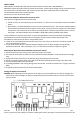
Setting the Upper Control Board
DANGER: When adjusting the zone switches on the upper unit control board, be sure the line voltage (115
VAC) and the control voltage (12 VDC) are disconnected from the board. Failure to do this could result in
injury or death.
Each zone must be controlled by an upper unit control board. When installed, this board is located in the
return air plenum of the rooftop unit. When installing the system, the upper unit control board must be set