TRT800H - OLED Mode S Transponder P/N 800ATC-H-(2xx)-(2xx) Operation and Installation (Document-No. 03.2124.010.
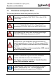
TRT800H / P/N 800ATC-H-(2xx)-(2xx) Operation and Installation Change History Revision Date Description of Change 1.00 18.11.2011 First Release 1.01 01.11.2012 Extended functions remote control interface and altitude compensation starting from software version 5.3 1.02 23.11.2012 Added information for TSO certification List of Service-Bulletins (SB) Service Bulletins have to be inserted into this manual and to be enlisted in the following table. SB No Rev. No.
TRT800H / P/N 800ATC-H-(2xx)-(2xx) Operation and Installation Table of Contents 1 2 3 3 GENERAL ..........................................................................................5 1.1 Symbols ...................................................................................5 1.2 Abbreviations ...........................................................................6 1.3 Customer Support ....................................................................6 1.4 Features .......................
TRT800H / P/N 800ATC-H-(2xx)-(2xx) Operation and Installation 4 5 3.8.1 Antenna Selection .......................................................23 3.8.2 Installation Recommendation ......................................23 3.8.3 Antenna Wiring ............................................................23 3.9 Post-Installation Check ..........................................................24 3.10 Starting Up .............................................................................25 3.
TRT800H / P/N 800ATC-H-(2xx)-(2xx) Operation and Installation 1 GENERAL This manual contains information about the physical, mechanical and electrical characteristics and about installation and operation of the Mode S Transponder TRT800H. The conditions and tests required for TSO approval of this article are minimum performance standards.
TRT800H / P/N 800ATC-H-(2xx)-(2xx) Operation and Installation 1.2 Abbreviations Abb.
TRT800H / P/N 800ATC-H-(2xx)-(2xx) Operation and Installation 1.4 Features In order to operate the Mode-S transponder it is necessary to request an ICAO 24-Bit Aircraft Address at the responsible national aviation authorities. The received Code is assigned to the specific transponder/aircraft and must be configured within the transponder. The 24bit Address is stored in an external memory which allows the transponder being exchanged without requiring any further configuration.
TRT800H / P/N 800ATC-H-(2xx)-(2xx) Operation and Installation 1.5 Deviations and Important Notes The following deviations have been granted by the FAA: The device is certified to FAA TSO-C112c in lieu of FAA TSO-C112d. Environmental Qualification Testing was performed according to RTCA/DO-160D in lieu of RTCA/DO-160F. The Software of this device was developed according to RTCA DO-178B Design Assurance Level "D".
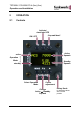
TRT800H / P/N 800ATC-H-(2xx)-(2xx) Operation and Installation 2 OPERATION 2.1 Controls Activate/ deactivate VFR ON / OFF „Squawk Ident“ Active Squawk active Operation Mode Standby Squawk standby Select Operation Mode Cursor adjustment Change Active Ù Standby Squawk 9 Rotary Knob for adjusting values at the cursor position Document-No: 03.2124.010.71e / Revision: 1.
TRT800H / P/N 800ATC-H-(2xx)-(2xx) Operation and Installation I/O VFR ON/OFF VFR ► Switch ON press button for approx. 0,5 s ► Switch OFFpress button for approx. 3 s ► activate/deactivate VFR Squawk (press shortly) ► store active Squawk as VFR/VFRW-Squawk (press button 3 s, →2.8) ► change between active and standby-Squawk ▲▼ CHANGE ► works as cursor back button (opposite function of the cursor button) during entering values and also for navigating backwards through the configuration menu (→4.5.
TRT800H / P/N 800ATC-H-(2xx)-(2xx) Operation and Installation 2.2 Switch ON/OFF Switch ON: press Switch OFF: press I/O for 0.5 s I/O for 3 s 2.2.1 Display information after power up After turning-on the display appears as follows (example): TRT800H. V5.3 Device Name FPGA-Vers: 102 Firmware Version 24D5F2 < BE2343 D4B3AA 000000 Software Version 000000 000000 000000 000000 If more than one configuration record is programmed the record selection menu appears (example).
TRT800H / P/N 800ATC-H-(2xx)-(2xx) Operation and Installation 2.3 Display - Indications Operational Mode: Active Lock out indication ACS Reply indication 7000 TM PLL/TRX/ DC SPI indicator | Test mode indicatior BAT/DIM Backlight setup IDT FL 030 Low battery ind.
TRT800H / P/N 800ATC-H-(2xx)-(2xx) Operation and Installation Value Meaning Remarks Error indicators PLL PLL Error Internal Error TRX Transmit Failure Check antenna and wiring DC Low internal voltage Internal error FPG FPGA-Failure Internal error BAT Battery Power too low maybe battery/generator fault 2.4 Display-Brightness In active mode (not standby) press ► for 2 s Display indicates “DIM” Æ Adjust brightness (DIM) with rotary knob Return to normal operation: press 2.
TRT800H / P/N 800ATC-H-(2xx)-(2xx) Operation and Installation 2.5.2 Configure Flight-ID Press MODE (repeatedly) until „STBY“ appears Press and hold ID while a counter is shown beside the active squawk. Release ID when “CHANGE FID” is displayed CHANGE FID __ ______ ABCDEFGH exit Enter Flight-Id with cursor button ► and rotary knob Enter FID left-aligned, without any blanks or dashes (!), e.g. 12345621DEFAV for the marking D-EFAV.
TRT800H / P/N 800ATC-H-(2xx)-(2xx) Operation and Installation If no 24-bit address (AA) was defined or entered as “000000“ the transponder works as Mode A-C transponder, in that case the following Modes are possible apart from Standby: • AC- Æ „Mode A+C“ Transponder replies only on Mode A and Mode-C interrogations. • A-- Æ „Mode A“ Transponder replies only on Mode A interrogations.
TRT800H / P/N 800ATC-H-(2xx)-(2xx) Operation and Installation • Display Standby Squawk: Press VFR or ▼▲ or use the Squawk remains active!) rotary knob (the VFR- Example: STBY 4700 7000 7000 FL 030 FL 030 FL 030 5600 STBY VFR VFR STBY 4700 VFR • Now the Standby Squawk can be adjusted by using the knob and activated with ▼▲. rotary • In order to store the current active Squawk as new VFR-Squawk (replacing the factory setting 7000): Press and hold VFR until an „S“ is indicated (approx.
TRT800H / P/N 800ATC-H-(2xx)-(2xx) Operation and Installation 3 INSTALLATION 3.1 Notes The following suggestions should be considered before installing. The assigned installation company will supply wiring. For diagrams refer to 3.7 Wiring. Transponder, External Memory, all cables and antennas shall be installed according to „FAA AC-143.13-2A Acceptable Methods, Techniques and Practices – Aircraft Alterations“ and the appropriate manufacturer’s instructions. 3.
TRT800H / P/N 800ATC-H-(2xx)-(2xx) Operation and Installation 3.4 Unpacking and Inspecting of the Equipment Carefully unpack the equipment and inspect for transport damages. If a damage claim has to be filed, save the shipping container and all packing materials as evidence to your claim. For storage or reshipment the original packaging should be used. 3.5 Mounting • In cooperation with a maintenance shop, location and kind of the installation are specified.
TRT800H / P/N 800ATC-H-(2xx)-(2xx) Operation and Installation 3.6 Equipment Connections 3.6.1 Electrical Connections One 15 pin D-SUB miniature connector includes all electrical connections, except for the antenna. Use only an External Memory Adapter TRT800EMxx as they are part of the certification and include a memory with the stored ICAO 24bit Aircraft Address. The (+UB)-wire has to protected by circuit breaker (2 Amp.)! 3.6.1.1 Mutual Suppression Other equipment on board (e. g.
TRT800H / P/N 800ATC-H-(2xx)-(2xx) Operation and Installation 3.6.1.3 Auto-On The Auto-On input allows to define how the transponder will behave when power is supplied to it. If the aircraft is equipped with a dedicated avionics master switch that switches the power supply to the transponder, the pin "Auto-On" must be wired together with the UB+ pin to the avionic master switch. The on/off button on the transponder is without function in that case.
TRT800H / P/N 800ATC-H-(2xx)-(2xx) Operation and Installation 3.7.2 Pin Assignment The transponder may only be operated together with an external memory address adaptor TRT800EMxx Pin Signal Remarks Adaptor Prev.
TRT800H / P/N 800ATC-H-(2xx)-(2xx) Operation and Installation 3.7.
TRT800H / P/N 800ATC-H-(2xx)-(2xx) Operation and Installation 3.8 Antenna 3.8.1 Antenna Selection • Recommended antennas: see section 3.11 Accessories • Choose an antenna type compatible with the vehicle and the mounting location. • Specified features depend on proper installation of the antenna. • The radiation pattern needs to be verified considering aircraft type and mounting location.
TRT800H / P/N 800ATC-H-(2xx)-(2xx) Operation and Installation Attenuation from antenna to transponder at 1090 MHz must not exceed 1.5 dB! 3.9 Post-Installation Check A certified maintenance shop must verify proper operation of the transponder by testing in accordance with Appendix F of “14 CFR Part 43 – ATC Transponder Tests and Inspections”. All steering and control functions of the aircraft are to be examined, in order to exclude disturbances by the wiring.
TRT800H / P/N 800ATC-H-(2xx)-(2xx) Operation and Installation 3.10 Starting Up Turn the transponder on with appear: I/O. After start-up the following screens TRT800H V5.3 2000 FPGA-Vers: 102 STBY 7000 FL 030 The TRT800H starts in standby mode (indicated with STBY). In order to change into operational mode (indicated with ACS) press MODE . If ground switch is connected and status “in flight” is selected TRT800H starts in active mode.
TRT800H / P/N 800ATC-H-(2xx)-(2xx) Operation and Installation 3.12 Drawings 3.12.1 Dimensions 65 mm Power/RS232 Static Air Antenna 65 mm TRT800 TRT800H Ø 57 mm 170 mm 15 mm 20mm 3.12.2 Mounting Advices Connections Area Panel Cut-out ≈ 80 mm 47,0 mm Ø 57,5 mm 4 x Ø 4 mm Fixing clips (spring) left / right 47,0 mm Connector (plug) has to be clamped with both spring locks. No screws may be turned in more than max. 15mm into the device – even if no hard limit is noticeable Document-No: 03.2124.
TRT800H / P/N 800ATC-H-(2xx)-(2xx) Operation and Installation 4 TRANSPONDER SETTINGS 4.1 Overview The TRT800H is capable of storing the following information: • ICAO 24-Bit Aircraft-Address (AA) • Aircraft Category (AC), • Flight Identification (FID) • Ground-Switch (Yes/No) • Speed Category (RI) • RS232 Interface Configuration All of these data are configurable in the Setup and are stored in the external memory module integrated within the housing of the D-Sub connector (included in the delivery).
TRT800H / P/N 800ATC-H-(2xx)-(2xx) Operation and Installation Page 1 Aircraft Address Aircraft Category Flight Identification AA : FE1234 AC : 19 FID: 44E123 next MODE Page 2 Speed Category Ground Switch option Remote Header option Speed Cat : 8 Ground Sw.: YES Remote Hd.: NO next MODE Page 3 RS-232 Settings: Protocol, baud rate, 1 position (if available) . RS‐232: NMEA Baud : 4800 Pos. : 48.1 9.
TRT800H / P/N 800ATC-H-(2xx)-(2xx) Operation and Installation • GPS receiver is connected and transmits data (if not: “Pos. :no data” is displayed) • a valid position is transmitted (if not: “Pos. :wrong data” displayed). is While configuration summary page is displayed no new position data will be processed. 4.3 General settings 4.3.1 ICAO 24-Bit Aircraft Address (AA) Setup→4.5.4 Ask your national aviation authority (e. g.
TRT800H / P/N 800ATC-H-(2xx)-(2xx) Operation and Installation Only one of the Codes mentioned in the table above must be used. 4.3.3 Flight-ID (FID) Setup→4.5.4 Per ICAO regulation Mode-S data must contain a valid flight identification (FID), to ensure that the correlation between flight plan and radar data will work automatically. FID setting is required to correspond to the aircraft identification that has been specified at item 7 of the ICAO flight plan.
TRT800H / P/N 800ATC-H-(2xx)-(2xx) Operation and Installation Code Description 08 No maximum airspeed data available. 09 Maximum airspeed ≤ 75 kt 10 75 kt > maximum airspeed ≤ 150 kt 11 150 kt > maximum airspeed ≤ 300 kt 12 300 kt > maximum airspeed ≤ 600 kt 13 14 600 kt > maximum airspeed ≤ 1200 kt Maximum airspeed > 1200 kt 15 Not assigned 4.4 Optional settings 4.4.1 Option Ground-Switch Setup→4.5.4 Wiring→3.7.
TRT800H / P/N 800ATC-H-(2xx)-(2xx) Operation and Installation standard user inputs available during standard operational mode. For more information see TRT800RT manual. Remote control interface de-/activation is setup configurable. Remote control interface must only be connected to TRT800RT. 4.4.3 Serial Interface (RS232) Setup→4.5.4 Wiring→3.7.3 Using serial interface a GPS receiver can be connected to broadcast own position via ADS-B Out position message.
TRT800H / P/N 800ATC-H-(2xx)-(2xx) Operation and Installation Option Description Baud rate FAVISIA Glas Cockpit support FAVISIA Data format to be processed in FAVISIA avionics suite. FAVISIA+GPS Data format to be processed in FAVISIA 4800 avionics suite (output) and additional processing of incoming NMEA GPSReceiver position data to support the ADS-B Out functionality Other Comm-A/Bsupport Data format for special purpose.
TRT800H / P/N 800ATC-H-(2xx)-(2xx) Operation and Installation The check for correspondence between the primary altimeter and the TRT800H is usually performed every 24 months as part of the aircraft's altimeter checks. Altitude correction is based on setup configurable offset values at five interpolation points ( 2000, 8000, 18000, 25000 and 35000 ft).The offset value itself is limited to a range from -100 to + 100ft at each point (10ft steps). 4.
TRT800H / P/N 800ATC-H-(2xx)-(2xx) Operation and Installation Count Displayed Name Function 25.28 Enter transponder general configuration pages ENTER SETUP 31..34 ALTITUDE CORRECTION 4.5.2 Enter altitude correction menu Transponder configuration/record structure Aircraft related parts of transponder configuration are stored in one out of eight possible records (record=presetting).
TRT800H / P/N 800ATC-H-(2xx)-(2xx) Operation and Installation 4.5.4 General Setup Any menu item can be passed by MODE. If no changes are made the original settings will remain stored. Modification of one menu item does not impact the others. No entries will be deleted. Step Display (Example) 1. Start-up Transponder 2. Ensure, the transponder-mode is „STBY“. If necessary change the mode by pressing MODE 3. 4. 5. Press ID A counter is shown at the upper-right corner.
TRT800H / P/N 800ATC-H-(2xx)-(2xx) Operation and Installation Step 6. Display (Example) With the rotary knob you can select „yes“ if a Ground Switch is installed, if not select “no” and proceed with step 7 Record 1: GND Switch: next Yes/No MODE 7. At this stage the respective speed category shall be selected by using the rotary knob. Record 1: Speed Cat.: next 08‐15 MODE 8. Record 1: At this stage a GPS receiver for ADS-B Out can be selected (Selectable by rotary knob). GPS/INT/EXT: NMEA/..
TRT800H / P/N 800ATC-H-(2xx)-(2xx) Operation and Installation Step Display (Example) 10. With ID further Records can now be created and configured as described in the aforementioned steps At start-up of the transponder one of the defined records with all associated configurations need to be selected Records ID=Edit Records EXIT MODE 11. You have now left the configuration mode and are back in normal operation. 2000 FL 030 STBY 7000 12. Switch Off the transponder 13. Switch On the transponder.
TRT800H / P/N 800ATC-H-(2xx)-(2xx) Operation and Installation 4.5.5 Altitude Correction Setup Description→4.4.4 Altitude correction setup shall be executed by qualified personnel only! Pilot and owner are responsible for correctly set altitude offset values. The use/setting of altitude correction values is only necessary in exceptional cases (see 4.4.4 for details) Altitude correction is based on five interpolation points ( 2000, 8000, 18000, 25000 and 35000 ft).
TRT800H / P/N 800ATC-H-(2xx)-(2xx) Operation and Installation Step 4. Display (Example) After release of ID the first altitude level + corresponding offset value is displayed. 5. Change offset value with knob Altitude: Offset : next 2000 ft 0 ft Altitude: Offset : next 2000 ft 0 ft rotary MODE 6. (..9) Repeat last step for another 4 altitude levels Altitude: 8000 ft Offset : 0 ft next/exit MODE 10. You have now left the configuration mode and are back in normal operation.
TRT800H / P/N 800ATC-H-(2xx)-(2xx) Operation and Installation 5 APPENDIX 5.1 Technical Data Compliance CS-ETSO-2C112a EASA.21O.
TRT800H / P/N 800ATC-H-(2xx)-(2xx) Operation and Installation Mounting Panel cut-out d=57,5 mm Weight 0,6 kg (1.32 lbs.) Receiver Characteristics: RF input power level resulting in a 90 % reply rate: Sensitivity A. MTL for ATCRBS and ATCRBS/Mode S All-Call interrogations: -74 dBm ±3 dB. B. MTL for Mode S interrogations: -74 dBm ± 3 dB.
TRT800H / P/N 800ATC-H-(2xx)-(2xx) Operation and Installation 5.2 Environmental Conditions Characteristic DO–160D Section Cat. Condition Temperature / Altitude Low ground survival temperature Low operating temperature High ground survival Temperature High Short-time Operating Temperature High Operating Temperature 4.0 4.5.2 + 70°C 4.5.3 In-Flight Loss of Cooling 4.5.4 Z Altitude 4.6.1 C1 Temperature Variation 5.
TRT800H / P/N 800ATC-H-(2xx)-(2xx) Operation and Installation Characteristic DO–160D Induced Signal Susceptibility Radio Frequency Susceptibility Emission of RF Energy Lightning Induced Transient Susceptibility Lightning Direct Effects Icing Electrostatic Discharge (ESD) 5.3 Section Cat. Condition 19.0 A 20.0 TT 21.0 M B3F 3 X No test required X No test required A 22.0 23.0 24.0 25.0 DO-178B Open Problem Reports There are no open problem reports for the software of this device. Document-No: 03.
TRT800H / P/N 800ATC-H-(2xx)-(2xx) Operation and Installation Notes: 45 Document-No: 03.2124.010.71e / Revision: 1.
Funkwerk Avionics GmbH Gewerbestraße 2 D-86875 Waal Germany phone.: +49-8246 9699 0 fax.: +49-8246 1049 E-mail: service@funkwerk-avionics.com www.funkwerk-avionics.