
Service manual

85
MAINTENANCE/INSPECTION PROCEDURE
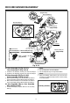
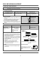
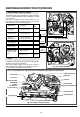
(4) F/E Head
(3) P1 Post
(6) Drum Assembly
(Video Head)
(5) Base
Assembly P2
(2) Tension Post
(1) Supply Reel
(7) Base Assembly P3
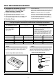
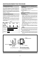
The following faults can be remedied by cleaning and oiling.
Check the needed lubrication and the conditions of cleanli-
ness in the unit.
Check with the customer to find out how often the unit is
used, and then determine that the unit is ready for inspection
and maintenance. Check the following parts.
1 Check before starting repairs
Phenomenon Inspection
Replace-
ment
Color beats Dirt on full-erase head
o
Poor S/N, no color
Dirt on video head
Vertical or
Horizontal jitter
Dirt on Audio/control head
Dirt on pinch roller
If locations marked with o do not operate normally after
cleaning, check for wear and replace.
See the EXPLODED VIEWS at the end of this manual as
well as the above illustrations See the Greasing (Page 87)
for the sections to be lubricated and greased.
NOTE
o
o
o
o
Dirt on video head
Dirt on tape transport system
Low volume,
Sound distorted
Tape does not run.
Tape is slack
o
In Review and
Unloading (off mode),
the Tape is rolled up
loosely.
Clutch Assembly D33K
Torque reduced
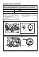
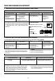
Cleaning Drum and
transport system
Fig. C-9-3
(8) A/C Head
(9) P4 Post
(11) Pinch Roller
(12) Take-up Guide Post
(10) Capstan Shaft
(13) Take-up Reel
* No. (1)~(13) Indicates the Tape Path to be traveled from Supply Reel to Take-up Reel.
Fig. C-9-1 Top VIEW
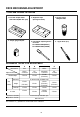
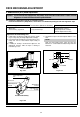
Fig. C-9-2 BOTTOM VIEW
F/E Head
Video Head
A/C Head
Pinch Roller
Belt Capston
Clutch
Assembly D33K
Fig. C-9-3 Tape Transport System