
Service manual


– 67 –
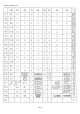
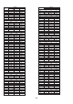
1~8 NC – Not used. (Connected to GND through a resistor)
9 VSS – GND.
10 VDD – Power supply.
11~12 NC – Not used. (Connected to GND through a resistor)
13 SDA I Connect to the TV microprocessor’s 12C bus line.
14 SCL I Connect to the TV microprocessor’s 12C bus line.
15 12C–CE O CE : 12C–SYS.
16 S–RD1 O DATA : 12C–SYS.
17 S–CLK2 O CLK : 12C–SYS.
18 S–SDO I DATA : SYS–12C.
19 NC – Not used. (Connected to GND through a resistor)
20 S–CLK1 I CLK : SYS–12C.
21~23 NC – Not used. (Connected to GND through a resistor)
24 VDD – Supply.
25 AVSS – GND.
26~33 NC – Not used. (Connected to GND through a resistor)
34 AVREF – GND.
35 AVDD – Supply.
36 RESET I Rest input.
37 NC – Not connected.
38 NC – Not used. (Connected to VDD)
39 NC – Not used. (Connected to GND)
40 X2 – 4.19MHz ceramic oscillator.
41 X1 – 4.19MHz ceramic oscillator.
42 VSS – GND.
43 POWER–IN I
Enter low power consumption mode (HALT) when both TV and SYS are “P-OFF.”
Cancel when either one is turned “ON”.
44 P–ON2–IN I
Enter low power consumption mode (HALT) when both TV and SYS are “P-OFF.”
Cancel when either one is turned “ON”.
45 MAIN–SW I “H” for low power consumption mode (STOP). “L” for cancel. *L fixed.
46 SS–CE I CE : SYS–12C.
47 TV–RMC O Control signal to TV microprocessor.
48~64 NC – Not used. (Connected to GND through a resistor)
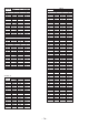
IC, UPD78F0034AYGC-AJD1UFLASH
Pin No. Pin Name I/O Description