www.aja.com Ki PRO Published: 1/21/10 Installation and Operation Guide B e c a u s e i t m a t t e r s .
ii Trademarks AJA®, KONA®, and XENA® are registered trademarks of AJA Video, Inc. Ki Pro™, Io Express™, Io HD™ and Io™ are trademarks of AJA Video, Inc. Apple, the Apple logo, AppleShare, AppleTalk, FireWire, iPod, iPod Touch, Mac, and Macintosh are registered trademarks of Apple Computer, Inc. Final Cut Pro, QuickTime and the QuickTime Logo are trademarks of Apple Computer, Inc. All other trademarks are the property of their respective holders. Notice Copyright © 2010 AJA Video, Inc. All rights reserved.
Ki Pro Installation and Operation Manual — Limited Warranty THE PRODUCT IS NOT INTENDED, STATED, OR WARRANTED TO OPERATE UNINTERRUPTED OR ERROR-FREE. YOU UNDERSTAND AND ACKNOWLEDGE THAT THE PRODUCT IS NOT INTENDED TO BE USED AS THE SOLE OR PRIMARY DATA SOURCE OR TARGET FOR CRITICAL DATA, AND THAT IT IS YOUR RESPONSIBILITY TO IMPLEMENT REDUNDANT CAPTURE AND BACKUP SYSTEMS AS APPROPRIATE.
iv
Ki Pro Installation and Operation Manual — Table of Contents Table of Contents Trademarks . . . . . . . . . . . . . . . . . . . . . . . . . . . . . . . . . . . . . . . . . . . . . . . . . . . . . . . . . . . . . . . . . . . . . . . . . . . . . . . . . . . . . . . . . . . . . . . . . . ii Notice . . . . . . . . . . . . . . . . . . . . . . . . . . . . . . . . . . . . . . . . . . . . . . . . . . . . . . . . . . . . . . . . . . . . . . . . . . . . . . . . . . . . . . . . . . . . . . . . . . . . . . .
2 Networking Ki Pro using a Static IP Address . . . . . . . . . . . . . . . . . . . . . . . . . . . . . . . . . . . . . . . . . . . . . . . . . . . . . . . . . . . . . 26 Networking Ki Pro using the Factory Default IP . . . . . . . . . . . . . . . . . . . . . . . . . . . . . . . . . . . . . . . . . . . . . . . . . . . . . . . . . 28 Test Ki Pro’s Network Connection with “Ping” . . . . . . . . . . . . . . . . . . . . . . . . . . . . . . . . . . . . . . . . . . . . . . . . . . . . . . . . . . .
Ki Pro Installation and Operation Manual — Table of Contents 50.4 STATIC GATEWAY . . . . . . . . . . . . . . . . . . . . . . . . . . . . . . . . . . . . . . . . . . . . . . . . . . . . . . . . . . . . . . . . . . . . . . . . . . . . . . 49 50.5 SYSTEM NAME . . . . . . . . . . . . . . . . . . . . . . . . . . . . . . . . . . . . . . . . . . . . . . . . . . . . . . . . . . . . . . . . . . . . . . . . . . . . . . . . . 49 50.6 MAC ADDRESS . . . . . . . . . . . . . . . . . . . . . . . . . . . . . . . . . . . . .
4
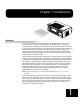
Chapter 1: Introduction Edge Shot Photo Here Overview Ki Pro is an all new way of connecting production and post. With it, you can now acquire with the same codec you edit with—Apple ProRes 422—in all 4 types (including HQ, LT and Proxy). Ki Pro simplifies the link between production and post by acquiring on the best codec for use with Apple Final Cut Studio, from virtually any camera, regardless of format.
2 Internally, Ki Pro natively supports the Apple ProRes 422 codecs in hardware, allowing realtime capture directly to Apple ProRes 422 QuickTime files. In fact, while the camera is recording to its own tape or file-based memory, Ki Pro can simultaneously capture the media as ProRes so it’s instantly ready to edit when the removable storage module is connected to a Mac. With this kind of flexibility, you can save time, steps, and get your project done quicker and with the highest quality.
Ki Pro Installation and Operation Manual — Features • Panel user interface features a VFD display (2 line character display), with 14 control buttons, 3 control knobs, and a power button • Storage Module (HDD) with FireWire 800 port for use with Apple Mac® computers (HFS+ file system) • 12 Vdc AC adapter with industry standard 4-pin XLR connector • 3-year warranty Software • Remote Browser control software. When a Mac®, PC, or 802.
4 Storage Module Options: SSD or Hard Drive • Ki Pro SSD Storage Module—although the Ki Pro comes standard with a removable HDD Storage Module, an optional SSD Storage Module is also available. The Ki Pro Solid State Storage Module (SSD) is recommended for mobile environments where shock-proof sturdiness may be needed. The Ki Pro SSD Storage Module offers the ultimate in media reliability.
Ki Pro Installation and Operation Manual — What’s In The Box? What’s In The Box? When you unpack your Ki Pro, you’ll find the following components: • Ki Pro CD-ROM—this CD contains documentation—including this manual you’re reading (PDF format). • Ki Pro Recorder • Ki Pro 250GB Hard Drive Storage Module and AC Adaptor • AC Adapter 110/220 with industry standard 4-pin XLR connector for supplying power to the Ki Pro. • Read Me First Notice—Contains late-breaking news and/or errata related to Ki Pro.
6 System Requirements AJA Video recommends that the Mac Pro or MacBook Pro used with the Ki Pro offer a FireWire 800 port and support Apple ProRes 422 with a satisfactory level of performance. Consult Final Cut Pro documentation when setting up and configuring your system for editing; ensure you have an adequate storage system (RAID array) and any needed video/audio interfaces.
Chapter 2: Getting Started Overview When using Ki Pro, you’ll make media cable connections to a variety of equipment based on how it’s being used. Chapters 2 and 3 discuss how to operate and use the Ki Pro in its many configurations—this chapter introduces the operating configurations, power supply options, plus all indicators, controls, and connections so you’ll have a working knowledge of how it can be used to tie together the worlds of acquiring media (production) and post-production.
8 Operator Side Slot LED Status Indicators show: Media Selected—Green Not-Selected—not illuminated Recording—flashes Green, On and Off Storage Module Release Button (press and hold button down while removing Disk Storage Cartridge) Expresscard Memory Slots (2) — 34mm 1-lane PCIe (press card in to mount; press again to eject) Storage Module (slides into slot) 1 2 VU Meters (2 Channel) STATUS 01 1 4% S SELECT CONFIG Audio Input Level Adjust (Press in and knob will pop out for easy adjustment) CLIP x
Ki Pro Installation and Operation Manual — Operator Side STATUS Button—Pressing the STATUS button, when not lit, enters the I/O Status menu. Pressing STATUS when it is lit turns off the Status menu and returns you to Transport mode. STATUS menus can be accessed at any time— including when the machine is in an active transport mode (PLAY, RECORD, FF, REV). The ALARM state displayed on the display shares functionality with STATUS. The Select buttons can be used to cycle through alarms and I/O status.
10 DELETE CLIP Button—Dedicated button that when pressed, deletes the currently selected clip. When pressed, the system displays a precautionary “ARE YOU SURE?” prompt. Press the up-arrow ADJUST button to say “Yes” and delete the clip, or the down-arrow ADJUST button to abort the deletion. When a clip is deleted, the next clip is then cued for deletion. Pressing DELETE CLIP, STOP or any other button—while the “ARE YOU SURE” prompt is displayed—cancels the delete operation.
Ki Pro Installation and Operation Manual — Operator Side Head Phone Volume Knob—To adjust headphone listening level, press the knob inward and the knob will then pop out for easy adjustment—just like the audio input level knobs. Displays and Indicators Alphanumeric and Graphics Display—Display details: The display is a 140x16 Graphics display. Normally, it will be configured in a 2x20 character format. All menus are designed to fit into this format, so some words may be truncated to fit the display limits.
12 Note: ExpressCard Memory is not supported in Ki Pro versions 1.0, 1.0.1, or 1.1. Visit the Ki Pro support page on our website for a list of AJA-qualified cards: http://www.aja.com/support/ki-pro/ki-pro.php Head Phone Jack—1/8” (3.5mm) miniature stereo TRS connection for standard stereo headphones. Connector Side Connect any camcorder, camera, or audio source—digital or analog—regardless of brand or format, to Ki Pro’s many connectors.
Ki Pro Installation and Operation Manual — Connector Side • HD/SD Component YPbPr/RGB Video, 3x BNCs for input, and 3x BNCs for output.
14 CVBS Composite NTSC/PAL Output One BNC connector supplies composite NTSC or PAL output. Connect the CVBS Out BNC to a monitor, or other Composite video device. Composite video signals are D/A (output) converted (10-bit). HDMI Two HDMI connectors provide for input and output of HDMI compatible video (version 1.1) and multi-channel embedded audio. HDCP is not supported on either input or output. The HDMI input is designed to support long cable runs: up to 100 feet (30.
Ki Pro Installation and Operation Manual — Power Connector (back of unit) CTRL/TC (FireWire 400) IEEE 1394a FireWire™ connector for connecting Ki Pro to a camera for timecode control. This connector does not support data transfer of compressed audio/video signals nor does it support connection to hard drives. Feature not supported in versions 1.0, 1.0.1, or 1.1.
16 Warning! Do not defeat the safety purpose of the polarized or grounding-type plug. A polarized plug has two blades with one wider than the other. A grounding type plug has two blades and a third grounding prong. The wide blade or the third prong are provided for your safety. If the provided plug does not fit into your outlet, consult an electrician for replacement of the obsolete outlet.
Ki Pro Installation and Operation Manual — Storage Removable Storage Modules (HDD or SSD) Although the Ki Pro comes standard with a removable 250GB HDD Storage Module, an optional SSD Storage Module is also available. The Ki Pro Solid State Storage Module (SSD) is recommended for mobile environments where shock-proof sturdiness may be needed. The Ki Pro SSD Storage Module offers the ultimate in media reliability.
18 Installation The following topic details set up and installation of Ki Pro. There are two different ways to set up and use the Ki Pro portable recorder: • Stand-alone use • Camera and mounting with optional Exo-skeleton (with or without a tripod) Software setup is the same for both uses. Choices you will make include how Ki Pro will be controlled (front panel, 802.
Ki Pro Installation and Operation Manual — Installation • Desk mounted in an AV media library, recording legacy material from a variety of decks, formats and sources, converting dissimilar media to standardized Apple Pro Res for archival. • Recording live house-of-worship services, Ki Pro sits on a shelf receiving a feed from a wall mounted remote camera and audio feed from the house mixer.
20 Exo-skeleton Setup and Adjustment The Exo-skeleton option has two configurations. As it comes out of the box, it contains an adjustable camera mount on top, a plate on the bottom for tripod mounting, and two thumbscrews for securing the Ki Pro unit to the Exoskeleton.
21 Ki Pro Installation and Operation Manual — Installation Alignment Pin Mounting Screw 2 Slide Mount off of Exo-skelton 3 1 Locate the Camera Mounting screw underneath (2 sizes provided), align pin to Camera base and tighten the Mounting screw to fasten securely. Replace Mount on Exo-skeleton when done, and tighten Locking Knob to lock camera in place.
22 Exo-skeleton Endplates and Rod Height Adjustment
Ki Pro Installation and Operation Manual — Installation Applying Power The installation and set up of a Ki Pro is straight-forward. If you’ll be controlling the unit from the front panel buttons and display, it’s ready right out of the box. Just cable the system’s audio and video sources, VTR(s), monitors, and audio equipment, mount the Ki Pro unit as desired, and begin recording. However, if you wish to control Ki Pro from a web browser or 802.11 device (iPhone etc.
24 In the event of sudden power loss, recordings that are in progress will not be written properly to the media. Note that there is a "Low Battery" warning prompt that users should take note of and stop recordings in progress if at all possible before battery failure. Ki Pro can sometimes manage to close the file before the battery stops providing sufficient power, but this is not always possible due to the nature of some batteries and the duration of some recordings.
Ki Pro Installation and Operation Manual — Remote Network Control Devices on a LAN have IP addresses which may be fixed and permanent, or dynamically assigned by the network (DHCP). When attaching Ki Pro to a LAN, you should first talk to your network administrator and find out how they want it connected (static IP or DHCP). Your IT department will be able to supply the information you need to install Ki Pro on a LAN. Caution! This device is a Class A product.
26 Here are the steps to communicate with Ki Pro after choosing the DHCP selection: 1. Use the Select buttons to navigate to parameter 50.2. Note on a piece of paper the DHCP supplied IP address shown. 2. With your laptop or desktop computer connected to the same LAN and DHCP enabled, type the IP address you noted in step 1 into the browser address bar. You should now see Ki Pro’s browser status screen.
Ki Pro Installation and Operation Manual — Remote Network Control 1 Note: for parameters 50.2, 50.3, and 50.4, you will be setting IP addresses that consist of “octets” separated by a period (i.e., 90.0.180.0). For these parameters, the Select button selects the octet and then the Adjust buttons select the desired number. Pressing Select again advances to the next octet. At the final octet, the address will flash—pressing Select at that point confirms the setting.
28 Networking Ki Pro using the Factory Default IP If you don’t want to use DHCP to network Ki Pro and also don’t want to set your own static IP address, you can simply use a Default setting to use a factory setting of 10.65.74.65. This might be useful for an application where you directly connect a laptop or computer to Ki Pro and want to get networking quickly. Here are the steps to set up this method of communication: 1. Use the Select buttons to navigate to parameter “50.
Ki Pro Installation and Operation Manual — Remote Network Control • Select a wireless network to connect to (as set on the access point you’ll communicate with). • Select the type of security, if any, to be used. If there is security, you’ll also enter its password. • Once configured, you can control Ki Pro from an iPhone or other 802.11 wireless device that supports browser control (iPod Touch et al). Wireless control of Ki Pro is managed using menus 53.1 through 53.
30
Chapter 3: Front Panel Operation There are three ways to control Ki Pro: the front panel, remotely from a web browser connected via ethernet, or a wireless browser (iPhone etc.) via 802.11. This chapter discusses controlling and using Ki Pro from its front panel. (Remote control via browser is discussed later in Chapter 4.) In Chapter two we discussed the panel controls overall, so ensure you've read and understand that material first.
32 Input Format Input selected Recording Format Audio input selected STATUS Menu (Record Mode) Current Clip Storage Slot Reel Number Remaining Capacity Timecode STATUS Menu (Play Mode) In the CONFIG or MEDIA menus, the Select buttons select various adjustable parameters, and the Adjust buttons adjust the selected parameter. When entering a menu, the system remembers and returns to the last selected parameter.
Ki Pro Installation and Operation Manual — TRANSPORT Mode (default) At any time you only need to hit any transport button to exit (or “exit” a STATUS, CONFIG, or MEDIA menu by pushing its button). Pressing a transport button sends the display into the TRANSPORT default menu. Several operations may result in an “ARE YOU SURE” interaction; for example, FORMAT MEDIA. This protects you from inadvertent actions and ensures that accidental button presses don’t have negative repercussions.
34 Playing Back a Clip To playback recorded media, you simply select the clip desired and press PLAY. If the clip you wish to playback is not currently selected, use the SELECT up/down buttons until the clip name appears on the display. Like recording, there is more than one way to initiate playback (front panel, web browser, and wireless). From the front panel these are the basic steps: 1. Press the STOP button to get to the TRANSPORT mode (if not already there).
Ki Pro Installation and Operation Manual — STATUS menus STATUS menus The STATUS menus display I/O status and Alarm information. The STATUS menu can be accessed almost anytime and will not change any active transport modes. Like the CONFIG and MEDIA menus, STATUS display screens can be viewed by pushing the SELECT up or down buttons. Pressing STATUS will exit the screens and return to TRANSPORT mode, where an action could still be occurring (like playback or even recording).
36 WARNINIG INVALID SELECTION WARNING UNRECOGNIZED MEDIA WARNING MEDIA IN USE Ki Pro features a variety of alarms to help you diagnose the condition of the unit, possible configuration issues, or possible signal issues. Here is a list of warning messages and their meaning: "WARNING Input Format Changed" prompt appears if a recording is started and the signal is lost or is changed. If this occurs, Ki Pro stops the recording that is in progress.
Ki Pro Installation and Operation Manual — MEDIA menus "WARNING Backup and Reformat" may appear if media has issues being mounted by the Ki Pro. As the prompt indicates, it is best to back up the media by copying it to another drive or disk array and then reformat the media.
38 16.2 DELETE CLIPS This parameter can be used to delete all of the clips on the media. 16.2 DELETE CLIPS DELETE ALL (default) KEEP CLIPS Delete all clips on the storage device when DELETE CLIPS is pressed or Adjust up arrow is pressed and held for 2 seconds No action (do not delete clips) The Ki Pro Storage Module can be used to hold data other than Apple ProRes 422 QuickTime recordings. If other files are saved to the Ki Pro Storage Module, they should be placed outside of the "AJA" folder.
Ki Pro Installation and Operation Manual — MEDIA menus Ki Pro offers these parameter choices for easy identification of the QuickTime files, so that the names can logically match the shooting script, and are acceptable when imported into the Final Cut Pro Browser window. Final Cut Pro's Browser window provides columns of data used to describe the media.
40 17.4 CLIP APPEND This parameter is used with parameter 17.5 ALPHA APPEND to append a text value after the CLIP NUMBER or have no text appended. 17.4 CLIP APPEND NONE (default) ALPHA No text is appended to the CLIP NAME and CLIP NUMBER The text value entered in ALPHA APPEND is appended to the CLIP NAME and CLIP NUMBER 17.5 ALPHA APPEND This parameter is used with parameter 17.4 CLIP APPEND to append a text value after the CLIP NUMBER. 17.
Ki Pro Installation and Operation Manual — CONFIG menus The exact choices displayed will vary depending on the parameter. Most adjustment choices made with the Adjust buttons take effect immediately and will be subsequently stored into the Ki Pro’s non-volatile memory if they remain unchanged for 3 seconds. If a Select or Adjust button is held down continuously, the changes will begin to happen automatically - with acceleration if applicable.
42 Note: A 23.98Hz source is automatically treated as PsF, regardless of this setting. For 29.97 Hz or 25 Hz, “NORMAL” means encode as interlaced and “PSF” means encode as progressive. This only applies to 1080 formats. VFR (Variable Frame Rate) recording makes use of meta data embedded in the RP188 data stream on the SD-SDI/HD-SDI input, allowing for the frame rate to change actively.
Ki Pro Installation and Operation Manual — CONFIG menus 1.7 COMPONENT OUT This parameter defines whether the component video output matches the file format or has the 1.5 OUT CONVERT selection applied to it. 1.7 COMPONENT OUT FILE FRMT (default) OUT CONVERT Output with the same format as the file Output using the selection in 1.5 OUT CONVERT 1.8 HDMI OUT This parameter defines whether the HDMI output matches the file format or has the 1.5 OUT CONVERT selection applied to it. 1.
44 3.2 COMPONENT OUT LVL This parameter selects the output level for signals applied at the component video output connectors. 3.2 COMPONENT OUT LVL SMPTE/N10 (default) BETACAM RGB Selects SMPTE/N10 output signal levels Selects BETACAM output signal levels Selects RGB output signal levels 3.4 NTSC CONFIG This parameter selects the output level for the composite video output connector. 3.
Ki Pro Installation and Operation Manual — CONFIG menus 5.1 UPCONVERSION This parameter selects the type of upconversion from SD performed, if set up to do so with parameters 1.6 through 1.8. 5.
46 5.2 DOWNCONVERSION This parameter selects the type of downconversion from HD performed, if set up to do so with parameters 1.6 through 1.8. 5.
Ki Pro Installation and Operation Manual — CONFIG menus 8.1 TC VALUE This parameter selects an hour for timecode to start. 8.1 TC VALUE 1 to 23 Use the ADJUST buttons to select a timecode hour. For example: 01:00:00:00, “02:00:00:00, etc. 8.2 TC TYPE This parameter selects drop frame or non-drop frame timecode. 8.2 TC TYPE NDF (default) DF Selects Non-drop Frame timecode Selects Drop Frame timecode 1 8.
48 41.3 AUDIO SG This parameter determines the audio signal output from Ki Pro’s internal test signal generator. 41.3 AUDIO SG OFF (default) Silence 1 kHz Turn audio test signal output OFF. Output an audio test signal containing silence only. Output a standard 1 kHz test signal tone. 50.1 IP CONFIG This parameter determines the type of TCP/IP network configuration used by Ki Pro. Note: With parameters 50.1, 50.2 and 50.
Ki Pro Installation and Operation Manual — CONFIG menus 50.3 SUBNET MASK This parameter determines the subnet mask used by Ki Pro for TCP/IP networking. 50.3 SUBNET MASK variable Using the adjust buttons, enter a subnet mask compatible with your LAN (if you have one). This is only needed for Static IP configurations. If 50.1 is set to DHCP, the default Subnet Mask will be assigned by the DHCP server If 50.1 is set to Default Addr, the default Subnet Mask is: 255.0.0.
50 50.6 MAC ADDRESS This parameter is an information only field showing the MAC address of the Ki Pro’s ethernet adapter. 50.6 MAC ADDRESS information only display Selecting this parameter allows you to view Ki Pro’s ethernet MAC address. The MAC address is a unique value associated with the internal ethernet network adapter. MAC addresses are also known as hardware addresses or physical addresses. MAC addresses uniquely identify an ethernet adapter on a LAN.
Ki Pro Installation and Operation Manual — CONFIG menus 53.1 802.11 CONTROL This parameter determines whether Ki Pro can be controlled remotely from a wireless browser. Enabling 802.11b/g control turns on the internal 802.11 radio. Parameters 53.2 through 53.5 must be set correctly to configure Ki Pro so it can be controlled. Ki Pro wireless control also requires the presence of wireless access point on the local LAN that it can communicate with. Note: Although Ki Pro has an internal 802.
52 53.4 802.11 PASSWORD This parameter defines the password used between Ki Pro, the access point and wireless browser clients—if any. 53.4 802.11 PASSWORD variable Using the adjust buttons, enter a password for Ki Pro. Using the adjust buttons and the top Select button, select the characters for the password. The adjust buttons scroll through the choices and the top Select button advances to the next character. While selecting characters, the character being changed will flash to show its position.
Ki Pro Installation and Operation Manual — CONFIG menus 54.3 802.11 SUBNET MASK This parameter determines the subnet mask used by Ki Pro’s wireless 802.11 transceiver. 54.3 802.11 SUBNET MASK variable Using the adjust buttons, enter a subnet mask compatible with your access oint (if you have one). This is only needed for Static IP configurations. If 54.1 is set to DHCP, the default Subnet Mask is: 255.255.255.0 55.4 DATE SET 1 This parameter manually sets the calendar date of the internal Ki Pro clock.
54 70.1 SCREEN SAVER When set to “AJA Logo”, a rolling AJA logo screen saver will appear on the alphanumeric display after 3 minutes of inactivity—defined as no button presses on the front panel. When the Screen saver is on, the STATUS button or STOP button will exit the screen saver. 70.1 SCREEN SAVER ON (AJA LOGO — default) Display horizontally rolling AJA logo after 3 minutes of button inactivity SYSTEM NAME Display the Ki Pro system name (defined in parameter 50.5). Screen saver is disabled.
Ki Pro Installation and Operation Manual — CONFIG menus Caution! Selecting this parameter and recalling factory defaults will overwrite the current settings (with the exception of network settings, which are retained). Recalling factory defaults does not affect these network settings: IP Config, IP Address, Subnet Mask, Default Gateway, System Name, 802.11 settings, or Date and Time.
56
Chapter 4: Browser Remote Control Remote Control Overview An optimized web server inside Ki Pro allows you to remotely monitor and adjust parameter settings via a a browser client, either running on a network wired computer or wireless device. The network can be a closed local area network, a straight computer-to-Ki Pro cable, or even exposed through a firewall to a broadband WAN (not generally recommended since anyone on the internet can then access the Ki Pro).
58 General Screen Information All Ki Pro web screens have certain areas in common. On the left of each screen is an information pane listing all the available Ki Pro screen choices. Click any of these items to jump to that screen. At the top of each screen you’ll also find a heading showing the connection status in addition to the Ki Pro’s serial number and software version. This latter information is useful if you ever have to call AJA Technical Support to discuss a problem or get help.
Ki Pro Installation and Operation Manual — Web Browser via Ethernet Resetting Values To Factory Settings To perform a global reset of Ki Pro to factory settings, go to Ki Pro front panel CONFIG parameter 99.0 for a reset to factory values. Config Screen The Config screen is a general purpose screen used to configure Ki Pro’s I/O choices, conversion choices, and also set up Ki Pro’s environment (name, clock settings, display etc.
60 Record Type (1.1): This parameter defines the frame recording method of media stored. RECORD TYPE can be configured to record the incoming video signal in a “NORMAL” manner, as a “PsF” signal if the incoming source is 1080psf 29.97 (for example), or VFR for variable framerate recording of the SD-SDI/HD-SDI input (such as Varicam). Arm Recording (8.3): This parameter selects how recording will begin: either by pressing record button (or web “Record” button) or via timecode.
Ki Pro Installation and Operation Manual — Web Browser via Ethernet 61 Video SG Format (41.1): This parameter determines the video format output from Ki Pro’s internal test signal generator. Video SG (41.2): This parameter determines the video signal output from Ki Pro’s internal test signal generator. This parameter is used with parameter above (41.1) to determine the type of video test signal output by Ki Pro. Audio SG (41.
62 Transport Screen This screen offers record, playback, fast forward, rewind and stop controls, similar to those available on the operator-side of Ki Pro. The screen also duplicates what is displayed on the Ki Pro front visual display, so you can see exactly what the Ki Pro operator/camera person is seeing. Ki Pro Web Interface, Transport Screen STOP : Press STOP to end playback or a media operation (PLAY, FF, REV, or RECORD). When stopped, Ki Pro displays the current point in the stopped clip.
Ki Pro Installation and Operation Manual — Web Browser via Ethernet Pushing the SLOT button cycles between unmounting media and selecting media. This function is only active when in the “STOP” mode and requires a “PRESS STOP TO CONFIRM” if not stopped. After you select a slot, the system returns to the last selected clip and timecode for that slot.
64 Available Ki Pros- Click to Refresh: all of the Ki Pro devices present on the same local LAN as the current Ki Pro are listed below this heading (see note below). The serial numbers of all Ki Pros on the LAN, or their defined “System Names” (see parameter 50.5) are listed—and clicking on any of these will bring up the Status screen of that Ki Pro. Note: the Ki Pro you control may be running a different software version so screens may look different.
Ki Pro Installation and Operation Manual — Web Browser via Ethernet Warning! Install this device in such a manner as to maintain a minimum of 5 cm (2 inches) separation distance between the radiating element(s) and all persons. This safety warning conforms with FCC radio frequency exposure limits. 802.11 Connection Status: shows the status of connection (connected or not connected) 802.11 IP Address Type (54.1): shows the type of IP address (DHCP, Static, or default) 802.11 Network (53.
66 Update Firmware Screen The Update Firmware screen allows you to update your Ki Pro to later versions of software as they are issued by AJA and posted on the website. When software updates are released, they often contain new features, improvements, and bulletins that may be very useful. We suggest checking the website when you have time.
Ki Pro Installation and Operation Manual — Web Browser via Wireless Upload and Install the Software on your Ki Pro Uploading and installing the software update only requires a PC or Mac that can “see” the Ki Pro via its ethernet connection. Follow this procedure to install the software: 1. Point your browser at Ki Pro's upgrade page by clicking on the “Update Firmware” link at the bottom of the navigation box on the left-hand side of any Ki Pro web page. 2. Click the “Browse...
68 Using Wireless Devices to Control Ki Pro Once an access point on the LAN is set up and Ki Pro is configured and enabled to communicate with wireless devices, making the connection is easy. Like using a web browser on a Mac or PC, wireless devices such as iPhones that have browsers can also be used to control Ki Pro. As in using a computer’s browser, the same optimized web server inside Ki Pro allows you to use an iPhones browser to load Ki Pro web pages for it.
Ki Pro Installation and Operation Manual — Web Browser via Wireless Access Transport Controls such as Record and Play View Ki Pro Status 1 Configure Input/Output and Conversions View clips list and select or delete clips Navigation Menu Choose Apple ProRes 422 Encoding Method and Make Media Choices 69
70 Status This iPhone screen displays the following controls and values: • I/O status including input format, record format, video source and audio source • Conversion status • Alarm status (OK or specific alarm conditions) Config This iPhone screen displays the following controls and values: • Out convert format • SDI output • Component output • 802.11 enable/disable • 802.11 security • 802.11 Network (SSID) • 802.
Appendix A: Specifications Video Input Digital: SD and HD-SDI (1xBNC), SMPTE-259/292/296 HDMI Analog: SD/HD Component (3xBNCS): SMPTE/EBU N10, Betacam 525 line, Betacam 525J, YPbPr 12-bit A/D, 2x oversampling Video Output (all simultaneously active) Digital: SD and HD-SDI, SMPTE-259/292/296 (1xBNC) HDMI Analog: Composite (1xBNC): NTSC, NTSCJ, PAL 12-bit D/A, 8x oversampling SD/HD Component (3xBNCs): SD: SMPTE/EBU N10, Betacam 525 line, Betacam 525J, RGB 12-bit D/A, 8x oversampling HD: YPbPr, RGB 12-b
A-2 Audio Output Digital: 24-bit SDI embedded audio, 8 channel, 48kHz HDMI embedded, 8 channel Analog: 24-bit D/A, 2 channel balanced XLR, 48kHz 2 channel unbalanced (2 RCA) Network 10/100/1000 Ethernet (RJ45) 802.11b/g wireless transceiver Embedded webserver for remote control Panel User Interface 2 x 20 character display, with dedicated buttons Timecode LTC timecode input and output via BNC SDI embedded RP188 timecode Control LANC Loop (2 LANC connectors)—not supported in Version 1.
Ki Pro Installation and Operation Manual — FireWire FireWire IEEE-1394b, FireWire™ 800Mb/s connects to Mac Pro or MacBook Pro (mount as harddrive)—not supported in Version 1.
A-4