PROTECT YOUR WARRANTY This unit must be installed by a registered, licensed installer as required by Government regulations.
Contents 2 Important Safety Instructions 3 Product Overview 5 Selecting the Installation Place 6 Installation 8 Technical Specifications 18 After Sales Support 1300 886 649 | info@tempo.
Important Safety Instructions PROTECT YOUR WARRANTY These installation instructions are for use by an appropriately qualified installer. Do not try to install the air conditioner on your own; doing so will expose you to danger and void the warranty. Contact a licensed installer. FOR THE INSTALLER Read this guide before installation. The appliance must be installed by a professional installer according to the instructions in this manual and in accordance with all applicable regulations.
Important Safety Instructions (Cont.) Installation • The air conditioner’s outdoor unit must be installed on suitably strong supports. • During installation of the indoor and outdoor units, do not allow children access to the working area. • Make sure that the base of the outdoor unit is firmly fixed, otherwise it will produce abnormal noise and vibration during use.
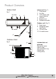
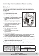
Product Overview Indoor unit (Fig. 1) 1 Front panel 2 Air filter 3 LCD display and signal receiver 4 Louvres 5 Supply cord 6 Remote controller Indoor Unit Fig. 1 Air inlet 1 2 3 5 4 Air outlet Outdoor unit (Fig. 2) 7 Drain hose 8 Refrigerant gas/ liquid pipe 9 Cut-off valve 10 Air outlet cover 56 67 Outdoor Uni t Fig.
Selecting the Installation Place Indoor Unit This Fixed Speed Split System Air Conditioner (9000 BTU) is suitable for cooling or heating a room of 10-20m2 in size. Before starting installation, decide on the position of the indoor and outdoor units, taking into account the minimum space required around the units.
Selecting the Installation Place (Cont.) Outdoor Unit If you put up a canopy to protect the outdoor unit from rain and sun rays, make sure you do not create any obstacles for proper heat dispersion from the condenser.
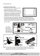
Installation Installing the Indoor Unit • First ensure the wall is strong and solid enough to hold the unit safety. • Attach the installation board to the wall using 4 (+) type screws. Use a spirit level to ensure it is in a perfectly level position vertically and horizontally, otherwise it might cause water drops when the air conditioner is running in cooling mode. • Pull out the indoor unit pipes after detaching the fixed parts on them.
Installation (Cont.) • Arrange the connection pipes, cable and outflow tube according to the illustration on the bottom of the previous page, then connect the drain pipe to the draining hole. • Use the insulation sleeve to wrap the position of the connection pipe and indoor unit, then wrap the insulating tape on the sleeve to avoid condensation water. • Fasten the connection pipes, cables and drain pipe together with a plastic strap.
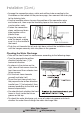
Installation (Cont.) Installing the Outdoor Unit • The outdoor unit must be firmly fixed so it does not fall over in strong wind. • Install the unit on a cement base, as illustrated below. • If the unit is to be installed in areas with strong wind, such as in coastal areas or at places high above sea level, the outdoor unit should be installed against a wall to ensure normal fan operation, and the blocking plate should be used.
Installation (Cont.) Pipe Connection • Connect the pipe to the unit as illustrated below. • Pointing to the centre of the pipe, fasten by wrench in the direction indicated in the illustration below, until it is tightly fastened. • Pointing towards the centre of the pipe, fasten the screw with strength. • Wrench the screw in the end until it clicks securely into place. After Sales Support 1300 886 649 | info@tempo.
Installation (Cont.) Shape and form of the pipe • Wrap up all pipe, water discharge and connection wire from top to below. • Cover the connections and fix them with two plastic rings. • Wrap up the pipes with tape alongside the wall and fix them to the wall with clips. These steps are usually adopted when the outdoor unit is installed below the indoor unit.
Installation (Cont.) Expelling Air from Pipes Air and humidity left inside the refrigerant circuit can cause compressor malfunction. After having connected the indoor and outdoor units, bleed the air and humidity from the refrigerant circuit by following the below steps. 1. Take off the cover from the stop valve and T-branch valve. 2. Take off the auxiliary cover from the T-branch valve. 3. Turn the stop valve rod anticlockwise to an angle of 90 degrees, keep it open for 8 seconds and then close the valve.
Installation (Cont.) As the air conditioner is filled with the refrigerant R410A, any air and moisture remaining in the refrigerant system must be discharged with a vacuum pump. (For method of using a manifold valve, refer to its operation manual.) 1. Completely tighten the flare nuts A, B, C, D (as illustrated below) and connect the manifold valve charge hose to a charge port of the lowpressure valve on the gas pipe side. 2. Connect the charge hose connection to the vacuum pump. 3.
Installation (Cont.) Electrical Connection • Unscrew the screw and take the control panel cover off the unit. • Connect the cable to their terminals according to their number. • Connect the grounded wire as follows: • Loosen the grounded screw of the electrical shelf. • Connect the grounded wire with the grounded screw, then set the screw in the mark. • Fix the cable to the terminal board with the fastening piece. • Reinstall the cover with the screw. Important notes • Don’t reverse the power polarity.
Installation (Cont.) Wiring diagram of constant speed Wiring diagram of variable speed • Note: Explanation for the power cord without plug (see below figure): NOTE: This manual includes all wiring modes for different air conditioner models. Please refer to the corresponding guide and instruction when wiring. We cannot exclude the possibility that the product has been improved, which could have caused a change of wiring, therefore please refer to the wiring diagram attached to the unit purchased.
Installation (Cont.) Test Run • Make sure that pipes and wires are properly connected. • Make sure that both the liquid side valve and air side valve are completely open. Power source connection • Connect the wire to an independent power source socket. • Prepare the remote control. • Run the air conditioner in cooling operation mode for 30 minutes or longer.
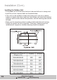
Technical Specifications AK-9000-F Fixed Speed Reverse Cycle Split System Air Conditioner Cooling Rated Capacity Rating Plate Parameters Heating 2500W Dehumidifying 0.8kg/h Rated Power Consumption Cooling 680W Heating 650W Rated Running Current Cooling 3.00A Heating 2.80A Max. Input Power 1000W Max. Input Current 5A EER Cooling 3.82W/W COP Heating 4.00W/W Power Supply Source 220-240V / 1Ph / 50Hz Refrigerant R410A Refrigerant Charged 1240g Max. Discharge Pressure 4.15MPa Max.
Technical Specifications (Cont.) AK-9000-F Fixed Speed Reverse Cycle Split System Air Conditioner Compressor Parameters Type Rotary Capacity 2160W Input 720W Rated Current (RLA) 3.3A Locked Rotor Amp (LRA) 19A Thermal Protector B140-135A-241E Capacitor 25µF Refrigerant Oil 350ml Outdoor Fan Parameters Outdoor Fan Motor Fan System Indoor Fan Parameters Indoor Fan Motor Type Axial Vane Number 3 Blade Material AS Diameter 408mm Insulation Grade B Capacitor 1.
After Sales Support 1300 886 649 | info@tempo.