,,0,f1't' SERVilCEMAN PARTSLIST 3 B 'roDEr GX.
é ' 0 ;.j-i-ii;'i s STEREO TAPE DECI( Mo,)',, GX'635D SECTION1 SERVICEMANUAL. LIST.. S E C T I O NP2A R T S S E C T I O N 3S C H E M A T IDCI A G R A M I ........43 ......
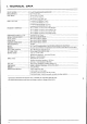
I. TECHNICAL DATA TRACK SYSTEM REEL CAPACITY TAPE SPEED 4 lrack 2 channel stereo/monaural system WOW& FLUTTER Lessthan 0.03%WRMSat 19 cm/s Lessthan 0.04%WRMSat 9.5 cm/s Lessthan 0.08%DIN 45500at 19 cm/s Lessthan 0.10%DIN 45500at 9.5 cm/s 30 to 27,000Hz 13 dB at 19 cm/susingWR Tape 30 to 21,000Hz 13 dB at 9.5 cm/susingWR Tape 30 to 25,000Hz t3 dB at 19 cm/susingLN Tape 30 to 19.000Hz 13 dB at 9.5 cm/s usingLN Tape FREQUENCYRESPONSE "0" VU) DISTORTION(1.
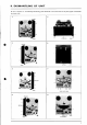
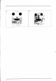
II. DISMANTLING OF UNIT In caseof trouble, etc. necessitatingdismantling,pleasedismantlein the order shown in the photographs.Reassemble in reverseorder.
)
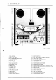
III. CONTROLS Fig. I 1 . P I T C HC O N T R O L 2 . S U P P L YR E E LT A B L E 3 . B U I L T - I NR E E LR E T A I N E R( L e f t } 4 . L E F T T E N S I O NA R M 5 . P I N C HR O L L E R 6. RECORDING M U T E S W I T C H( R E CM U T E ) / T I M I N GL A M P 7 , R E E LS I Z ES E L E C T O R 8 . R E V E R S ES E L E C T O R 9 . P O W E RS W I T C H 1 0 . V U M E T E R( R i g h t ) 1 1 . V U M E T E R( L e f t } 1 2 . T A P ES E L E C T O R 1 3 , T A P ES P E E DS E L E C T O R 1 4 . T I M E RS T A R T 15.
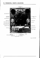
IV. PRINCIPAL PARTS LOCATION BRAKEMICROSWITCH sw906 BRAKE PLUNGERSL9O3 RNCH ROLLER PLUNGERSL9O2 PIÍCH CONTROLVOLUME VR9OI REALTIME COUNÍER PAJSE PLUNGERSL9O4 TENSION ARM(R) TENSIONARM(L} REC MUTE SWITCH SW9O4 HEADBLOCK REEL SIZE S1,VITCH SW9O3 REVERSESELECTORSWITCH POWERSWTTCHSW90l OPERATION ELOCK RECMODEINOICATOR ",n,.** M I Cr l- RÊc LEVEL VOLUME rrrup J {.
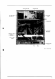
REMO,CON JACK J9O5 REEL MOTORRIGHT M902 24XO-TD VOLTAGE SELECTOR FUSE PC BOARD TH-20rro SYS.CON PC BOARD TH-rOr5 CAPSTANMOTOR M903 SCM-200 OPERATIONP,C BOARO TH-2041 OPERATION P.CBOARO ÍH-2042 VOLUME PC BGRD TH-5002 PRE AMP PC BOARD TH-500r4 Fie.
V. CIRCUIT OPERATING PRINCIPLES 1.
0 ll tl t 3o .3d:j* HTiY usF i I a! ,oi"dado _:i|.@ lq m ':,.+. q +, E i^ -_.--;-È I r !t '.11 r ; ; : ,:' :; ;r,: r t. :.-:-.. ' r aJ4s -,r:(--!J I Í l !r { ql l= 3i TÍ :l 11 Í tJ::'"'. :ln | \ ; ê óL "ri+*:rBe J lío lHs i3 io! u F o ? * gI r'_f $ ó"f|e L t É -L . Í li 6 l :' t jó51 \t.
-È it ii J ."*,ffi't" i* *" ;:Tm!!!@ * A ; -= , 1 ' - o - : - - - _ . . ! ; _ Ë ^ I tgv , : ' . } l I r + ' r r q;-r+;r;+;-;JPF t o í l L j "':ï'r; l3l ,t:'*f;U; * * 'i: .ffilMffitutu Ë _t-.-_--_l_ I r r lgo lH3 !.' l;* l:;:r : '"ioq i | tdi t, .--:-..
I I I Y i L .+. || I _l ',rr# tr--9\#r* l l ió I| r I ", i ,r/\ | ' = , i :I ' li fi.> it_Yli: nit"" l*.eir ! Y * lt :ir rl -- Q .*t .- ' Q . r '"il-l"I't'i | l+' ::i '.-,'."-lvr+ = : v l - L - I *llr+,ir-*---. Èlii L!- ï lá--'# t"; -ràÈllá -, i ;, j..J l'-t.,, :r.* iii ' Ï ' r : ' I" rè, " i Y _ T T -l:]í:Itl 'iià,i' :l:; i "iiài .èàà: .,;;i '-;:it: i !qi :! : '€ 3o o3 - o ai fd f -r* t;1"-I -at : ! Í e a . r y l . / 1 .. !o@ w LMr .a:/n@ 'i.,+, & t. ? t. .
a (> l'."r 3g L ó C,oirE L..l É g i:l x! | -.
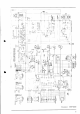
I El , !: r!: I 6 uï t I Irl @ l;A * Schematic-5 REV-REC MODE 15
ffi*e l : i a;-*J ^t r,Ër .*:l to I H r3 i:. tIo t-s I ,lii@&g 'gi 4F.--..:\io 1.9 rlr,,.'::,p , :.t I t15 L.1,--áÈ.. I +alC)J lË3 :ory l d rts d ar-) {'ll I lÍ rJ3iil: ?qn * 3-t :: c: zl t < Cl ó i l l rlg ' T 'lËË l6É {.
ï i,t l l !*J _ n i i t r lËil I È"i ; " 0 LT]iIJ I ; ;l:9 ï=ï1 ti.F#' 'iii: l:! | lillir raát: t . "I -àL o; l': ..Ll r('li lJ ! q$ i5= l> É t a Ê l ! L u.t;Ft; .9íii i " tr :Èi i è:3 I L@_ + grt tÈq ::.J I z'i 3e o3 @l tsr HÊ iàil i6 1__l o 'Rt' qíïË l! --.,l o 9; :t !: El r,;;i [Áq .;,"*.*". ". ., ói'tdh*ode :rÍ @tunffi 'ii+, ,m l"ft t' ,1L--_..-l*E l , r l:
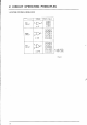
I-I. CIRCUIT CONSTRUCTIONOF ICI M544IOP The designoi M54410Puntil now tradSTOP,pt-nY. g R as R E C , F F , R W D ,P A U S Ea n d R E C p r e v e n t i n A its input terminals. GX-635D circuit is constructed with FWD in place of PAUSE and REV in place of PLAY. Pause is controlled by a flip flop with a separateIC. l) Block Diagram T I I ST ) I --'l 4 . , '-\)7 I I I FAST FF /. 1 I @ F i g .
2) Terminals and their functions TerminalFunction Terminal Name lnput terminalfor stoppingoperation STOP Input terminal for fast forward FF Operation input terminals RWD Input terminal for rewind FWD Input terminalfor playbackin the forwarddirection REV Input terminalfor playbackin the reversedirection REC- Input terminalfor recording Input terminalfor preventingrecording "H" signaloutput duringfast forwardor rewindmode Terminalwith "H" Terminalwith signaloutput duringfast forwardmode "H" Termi
VELOCITY+ PULSE WIDTH CONVERSION r\ 501 @ Fig.5 Block Diagram I-2. CIRCUIT FOR PREVENTING CLICK NOISE DURING TIMER RECORDING l) When the power is turned on for timer recording, recording must take place after the amplifier circuit is in full operationor elseclick noisewill be recorded.Also when the power is turned off, Rec Final Mute must operate before the amplifier circuit ceasesto operateoÍ elseclick noisewill be recorded. This circuit prevents such click noise from beingrecorded.
3-3/4 +7-l/2 É Í s E R Voou r P U n lx lo ó t - TR4 R4 220 cro ooilí t \: :+ ! _ . a8. '_.\ E2 n I TR5 I 9l ( /l r R r o *á = [ *l r. .-r-- t5 2,?K ÍR6 = l È \ ", TR7 ( ( Át q i T_ TR12 CtA t/tOO E IR€ ; 3: -O- t: t I 9; e Í - I \j 9 x r ó 3 I I K D9 ---1 r. I iL _n_ t r t AADE q E ry L I __J MoToE FÀPSTAN TR13 : rK8 lprrrclrJoNrRoll Fig.
2) Explanation of the circuit operation (Refer to F i g s .6 , 7 ) The velocity signal obtained from the motor's frequencygeneratoris shapedinto a waveformin the period of "T" proportionateto the velocityas in (a) on collector TR6. This signal is differentiated and enters TR7 base.This makes TR7's collector output as in (c) and turns ON TRl0 duringthe time of the negativepulse. Meanwhile TR8 baseis suppliedwith a waveform like (d) and when it reachesthe thresholdlevel, TR8 is turned on.
VI. MECHANISM ADJUSTMENT A D J U S T I N GW A S H E R (U TYPE) I E N S I O N I V I C R OS W I T C H A D J U S T I N GW A S H E R (U TYPE) Fig.8 RollerBlock 1. GUIDE ROLLER LOOSEPLAY ADJUSTMENT(Referto Fig. 8) Adjust the stopper(roller pulley on the right) screw (d) so that the loose play gap is approximately 0.1 mm when the guide roller is moved as indicated by arrowmark in Fig. 8. 2. TENSIONMICRO SWITCHPOSITION ADJUSTMENT(Referto Fig. 8) 3. ROLLER BLOCK HEIGHT ADJUSTMENT(Refer to Fig.
FIXATION NUT REEL TABLE FIXINGSCREWS ADJUSTMENTSCREW Fig.l0 Fig.9 4 . REEL TABLE HEIGHT ADJUSTMENT (Refer to Fig. 9) I ) Temporarily screw in the fixing screwsleavinga gap of 15 mm between the reel table and the chassisboard. 2) Run the tape and adjust the height of the reel table so that the tape is taken up in the centerof the reel. Tighten fixing screws. Adjust the height of the right reel table at fast forward. of the left reel table at rewind. .A L- 5.
í''*' À\ BRAKE MICRO , swtTcH \ o BRAKELEVER ERAKELEVER Fig. I I 55os!5og Fig.l3 € E IL F i g .1 2 6 . BRAKE BAND POSITION ADJUSTI\{ENT AND BRAKE TENSION ADJUSTMENT (Referto Figs.11 to 13) 1) Adjust the brake lever to 180" position by loosening the screws(a) and (a'). 2) Work the brake plunger to check that the brake band is not slanted. 3) Adjust the position of the part with screws(b) and (b') to obtain a brake tension of 550 1 50g on both brakesat stopmode.
sYs.coNPc TH- r0t5 V R 2s O K B (7-l/2in) VRI 5OKB (3-3l4in) F i g .l 6 10. TAPE SPEEDADJUSTMENT (Referto Fig. 16) Set the Tape SpeedSwitch to7-l12 ips and playback the I ,000Hz,7 -l 12 Testtape. Connect a frequency counter to LINE OUT and adjust VR2 50 kB until the counter reads1,000Hz !0.5%. Next, set the Tape SpeedSwitch to 3-314ips and adjust VRI 50 kB until the frequency counter reads 500 Hz t0.5%.
VII. HEAD ADJUSTMENT TAPEGUIDEHEIGHT NUT ADJUSTMENT PLAYBACK HEAD P4-241 RECORDINGERASE HEAD HEAD R4-241 E4-241 ERASE RECORDING HEAD HEAD R4-241 E4-241 Fig.
S t e p Adjustment Item TestTape Supply Signal Mode Adjustment Point Remarks Tape Guide Height Optional Tape Guide Height FWD Adjustment Nut FWD Recording HeadHeight Optional FWD FWD Erase Head Height Confirmation Optional FWD FWD Playback Head Height Optional FWD (d) (e) (f) FWD Playback Head Azimuth Alighment 8,000Hz 3-3l4ips TestTape FWD (f) Maximum output, both channels.
VIII. AMPLIFIER ADJUSTMENT TC2 TCrbrczb VRI I IVR2 VRIb VR2b Fig.
Step Adjustment Item TestTape Supply Signal I FWD Playback Level 700H27-l 12ips OVUTestTape FWD 2 REV Playback Level ips 7O0Hz7-112 OVUTestTape REV VU Meter Sensitivity ips 700H27-l12 OVUTestTape J Mode Adjustment Point Result VR3 50 kB 0t0.5dBm Remarks (0.77sv) VR4 010.5dBm s0kB (0.77sv) FWD VR5 lkB OVU indication , FWD Recording Level Scotch#2ll Tape 1 , 0 0 0H z 0 d B m Recording F\ryD-REC VR2 1 0k B 0t0.
IX. DC RESISTANCE OF VARIOUS COILS Designation DC Resistance Main Motor SCM.2OO BetweenBLU-RED: I l0 ohms BetweenYLW-BRN: 170 ohms Pick-up Coil: 665 ohms Reel Motor 24XO-TD BetweenBLU-RED: 30 ohms BetweenYLW-BRN: 157 ohms Pinch Roller Plunger I664TLT 700 ohmst10% Brake Plunger, REV Plunger 124OTLT 600 ohms110% PausePlunger TDS.OTA 696 slynsr10% Relay FRL.264 6596665r 15% Part BR2II Relay 1 , 2 9 0o h m s1 1 0 % Relay LAB2NS I , 7 5 0 o h m st 1 0 % EraseHead E4-24r 2.
2. COMPOSITION OF VARIOUS P.C BOARDS 1) SYS.CONP.CBOARDTH-1015(4ED),REVERSEP.CBOARDTH-2044, SENSINGP.CBOARDTH-2045& RECMUTE P.CBOARD TH-2O46 .a [ J r ËV dt:Ëz\ q'q á-êl-sil E]J v : ] @ | 5. 3 tÈl lib.-è _ t " _ i r- " 11ï .fl t l I f/sHqÍ 8Lx I - i t -J l, i ' 1 2 ;= J IrEl lEsl n_^.
3) VOLI.]MEP.CBOARDTH.sOO2 TH-5001A l r H -s o o r a T H - 5 0 0 ra ]ru-soora -l r.t rï*1 @ o c rwl vR I 5OKA rÏ*-l lï rCl T tLrNEI 4) DIRECTIONP.CBOARD TH-2043(2ED\ @ Í7h I'W LT 0 4 sR- to50 @ lFausE-l !i'Íht vo@ v ? r i ? l l ÍFwpl o.lJ"n,tfr1nr o,?3",ífr4 \zt ty @o ^ ? ? i i s) oPERATTONP.C BOARD(A) TH-2041(2ED) & OPERATTON P.C BOARD(B) TH-2042(2ED) O P E R A T I OPNC B O A R D ( A ) Í H - 2 0 4 1 lFÁrrÉt Fld r^r \y \ ? ;t È. r\ \-/ @ í^ tly N 6\ \:2 ? :+ d.
6) FUSEP.C BOARDTH-2040(U/T) --oi o I ---@ | I I il [l ual o_ o t:l o l e7 \ l i: l = t3 I g< aj-:ir i -*-1 ;r --- - II aT__)i'@------- I I\ l - l rI l io I l ïl T r * l t - I L I ï 3Y =r o @
7) FUSEP.C BOAR-DTH-2O40(JPN,AAL, CSA) l$11rzovvr-w roi T t : I - L --{@ ii _ -+l - , --T-- | r l i > a O o ii < P - i T . o r i + \ t + 4"1 i I . t i - o ---1 | tActrot6oHtl A @ || oor/r2oe) aÀL,csa ,rPNo.olll.4Kv iD ki @-l l I lAcoovI I 5Ol6OHzI " o d o @ @ -]- -]e-r- < t < l T Y L I O Y L I I-]- ; E-L I ugl sz
8) FUSEP.C BOARDTH-2040,(CEE,UK) sw905 240V ,rt 'l 220V tr- E (9 t ]rr-rors Irrpt I -JnËrr-uoron I RIGHT J R E E LM O T O R @/z4of1 uKl rcEE, ]rn- rors W A R N I N 6A: r N D l C À T E S A F E Í Y C R I T I C A LC O M P O N E N TFSO R C O N Í | N ! € 0 S A F E T Y , FEPLACE SAFElY CRITICAL COMPONENTS ONLY WITH MANUFACTURER'S RECOMMEflDED PARTS À ! F F _ . 5 S fV L N _ : ^ L r \ O O U L F S . O M P O S A N T C S R t T T O U EO SE S U n e t r .
SECTION 2 J PAFITS LIST TABLE OF CONTENTS SPAREPARTSLIST. . RECOMMENDED HEADBLOCK MOTOR(SCM-200)BLOCK R.EELTABLEBLOCK ROLLERBLOCK POWERSI.JPPLY BLOCK M E C H AA S S E M B LBYL O C K P . CB O A R D S (1) SYS.CONP.CBOARD(TH-l0ls) BLOCK (2) PRE AMP P.C BOARD(TH-5001A)BLOCK (3) voL.P.CBOARD(TH-5002)BLOCK (4) REC,LEDP.CBOARD(TH-50018)BLOCK. BLOCK 9 . AMPASSEMBLY 10.F I N A L A S S E M B L Y B L O C K SEMICONDUCTORS 1 1 .LISTOF INTERCHANGEABLE INDEX . . .46 .......48 .... ...50 ......5I ....52 . . .54 .. ..
HOW TO USE THIS PARTS LIST This partslist is compiledby variousindividualblocksbasedon assemblyprocess. \ilhen orderingparts,pleasedescribepartsnumber,serialnumber,and model numberin detail. How to read List - The referencenumbercorresponds with illustrationor photo numberof that particular parts list. This numbercorresponds with the FigureNumber. number correspondswith the individual parts index number I r-This in that figure.
AC INLET SYSTEM This model is equippedwith an AC INLET SYSTEM.Pleaserefer to the AC INLET SYSTEMCHART below for the from the model specifictype. By the AC INLET SYSTEM,AC (mains)cord can be connectedto and disconnected becausethe model is providedwith socketexclusivelyfor AC (mains)cord on its main body. Pleasenote, however,that certain modelsare not equippedwith this systemand has a built-in AC (mains)coÍd as before. AC INLET SYSTEM CHART CLASS II CLASS I .
1. RECOMMENDEDSPAREPARTS LIST Because,if the parts listed below are on hand, almost any repair can be accomplished,we suggestthat you stock these Recommended SparePartsItems. PartsNo. 46 Description Note 84308262 Sys.Con P.CBoardComp.GX-63sD(U/T) (JPN) 8A308263 Sys.Con P.C BoardComp.cX-635D (CSA)(AAL) 84308264 Sys.Con P.CBoardComp.cX-635D (CEE)(UK) BA308275 PreAr4p P.C BoardComp.GX-635D(U/T) (JPN,CSA,AAL) 8A308296 PreAmpP.CBoardComp.cX-635D(CEE)(UK) 8H308217 HeadBlock Comp.
PartsNo. Note Description ES3I 3792 A sticesw. TSSor2l83 8S3089I 4 PushSW. SUFI2 ES3089I 3 R o t a r yS W . S R U I 0 2 3 5 85308925 P u s hS W . S U F 1 2 F,5313622 2\ PushSW. JP-27(w/o lavel) E5309059 I PushSW. JP-27 CSA,AAL 8S3090s8 I PushSW.JP-24 CEE,UK 8S309094 SlideSW. SL|3-6-6-2-2-B E530143s Slide SW. CL-2108 E5308984 PushSW. SUF44 83308983 PushSW. J-K2023 E3301436 SlideSW. CL-206E ES301 715 S l i d eS W . S S B 0 2 2 1 4 85306292 Leaf SW.
2.
2) HEAD BLOCK ft:l' $ Parts No. Description Head Block Comp. GX-635D S p r i n g W a s h e r ,M 4 Sctew, pan head 4x8 Tape Guide (A) T a p eG u i d e P r o p M3 Nut, #2 Angle Adjust Spting (E) T a P eG u i d e ( C ) Head Sub Chassis E R H e a d B a s e( A ) E R H e a d B a s e( B ) Angle Adjust Spring (B) PB Head Base S c r e w , . p a nh e a d 3 x l 2 S c r e w ,p a n h e a d 3 x l 0 ER HeadAngle(A) ER HeadAngle(B) P B H e a dA n s l e ( A ) PB Head Angle (B) P.C Board Terminal Plate ERASE HEAD 84.
3. TLLUSTRATIONOF MOTOR(SCM-200) BLOCK 1 2 ii 10 9 3) MOTOR(SCM.2OO) BLOCK @- i L Pef 1i;. 3 - 1x 3-2 3-3 3-4 3-5 3-6x 3-7 3-8 3-9 3-10 3 - 11 3-12 P a r t sN o . D e s c r i p ri o n BM3O83l0 Motor BlockComp.
4. ILLUSTRATION OF REEL TABLE BLOCK $ s 4) REEL TABLE BLOCK ft:: 4-lx 4-2 4-3 4-4 4-S 4-6 4-'l 4-8 4-9 4-lO Parts No. DescÍiption 8 R 5 8 7 5 5 3 R e e lT a b l e B l o c k C o m p . TE (Take-uP) MS34200o Reel Shaft ZGS4O6|7 ClamperSpring M't534611 Reel Clamper ZW27OO88'E'Ring 1.9M MTs34688 Reel Table Rubber Z S 4 l 9 6 1 O S c r e w ,p a n h e a d 3 x 1 2 MT43ó86O BrakeCloth Comp. MR 2G317496 Felt Tension Spring 2 5 4 2 4 0 5 6 S c r e w ,p a n h e a d 4 x l 0 Schenatic No.
5. LLUSTRATION OF ROLLER BLOCK 2.7 28 2.9 2I 26 20 24 19 16 11. 23 i\ ó --..
5) ROLLER BLOCK ft:l' . O Parts No.
6.
6) POWERSUPPLYBLOCK ft:l' ParrsNo. Description Schematic FUSE P.CBOARD BLOCK 6-l x 6-2x 6-3x 6-4 6-5x 6-6x 6-'7x 6-8x 6-9 6-10 6-r l t $ 6-12 6-13 6-14 6-15 6-l 6 6-17x 6-18x 6-19x 6-2ox 6-2lx 6-22x 6-23 6-24 6-25 6-26 6-27x 6-28x 6-29x 6-3ox T 6-3lx 6-32x 6-33x 6-34x E C 55 l 1 6 0 A C e r a m i c / C .l ) B 8 2 t N A o . 0 1 p F( Z ) 1 . 4 k w v ( U i r , J P N ) E C 2 9 4 l l 8 À C e r a m i c / C .I ) P N ó 6 0 0 Y M o . ol p l .
7.
7) MECHA ASSEMBLYBLOCK Ref No. 7-l j-2 7-3 '7-4x '7-5 ' 7- 6 '7-'7 7-B 'l-9 7-lO 't-r1 7-12 {,r Parts No. Description COUNTER BLOCK MC3O8242 Counter Part MP499-O7 EV3o89i? vol.VMloE I kB PAUSE PLUNGER BLOCK E P 3 O 9 0 5 6 P l u n g e rT D S - O ? A 255923'78 Screw,pan head 2.6x3 Z W 3 1 3 5 9 3 W a s h e r( P B p ) I ) 5 . 1 x 1 o . 3 x 0 . 5 t ZG3O8134 Joint Spring ZWz1OOa8 'E'Rine l.9M SW. BLOCK F]S3O89l4 FlS3089l3 25422076 ED69882ó E S 3 0 8 9 25 P u s hS W . S U l t l 2 R o t a r y S W .
8. P.CBOARDS (1) SYS.CON P.CBOARD(TH-101s)BLOCK SY-mh'l N()(r ),r (t)-2 (l ),3 P a r t sN o . Schematic No. Description F.I308e36 E143o66l Ijr633e60 EIs7384o [.T3t2497 (r )-TR2 ET63e43' l (l )-TR3 FlT3o7349 (l)-TR4to8 ÉT639437 ( l ) - T R 9 . l0 E T 5 s 4 6 s 7 (l)-TRl I ET63e43? ( r ) - T R r2 ETss46s'7 (l)-TRl3 ET308947 (l)-TRl4,f s ET63943'7 ( l ) - T R l 6 t o 1 9E T 3 0 8 9 3 7 (r )-TR20 !Ts22268 (1)-TR2l FrT399846 ( I ) .
(2) PRE AMP P.CBOARD(TH-s0014)BLOCK Svmbol P a r t sN o . Description (2)-r BA308275 Pre Amp P.C Board Comp. GX-635D(U/T) ( J P N ,C S A , A A L ) Pre Amp P.C Board Comp. GX.
9.
9) AMP ASSEMBLYBLOCK ft:l' Parts No. Description 9-l 9-2 9-3 REVERSEPLUNGERBLOCK EP31044? PlungeÍI24OTLT MB6O67l2 StopperRubber KJ 25422076 Screw,pan head3x5 9-4 TIMER BLOCK 82308285 Timer BlockComp.GX-635D 9-5 9-6 9-'l 9-8 9-9 9-l 0 9-l1 9-12 9 - 13 9-14 9-l 5 9-l6 AMP ASSEMBLY BLOCK 25325495 Tapping Screw#2, 3x6 (BR) 2544784O Tapping Screw#2, 3x8 (BR) 2w263946 Nylon Rivet 4x5 M Z 3 0 l O 8 4 R e v e r s eJ o i n t M L 3 0 l 1 2 3 R e v e r s eA r m Z G 3 O I O ' 1 2 R e v e r s eS W .
IO. PHOTOOF FINAL ASSEMBLYBLOCK 38 39 35 37 36 49 16 20 13 19 23 11 45 12 \_ 18 27 21 14 44 11 -' ,g 43 :':ai' t.Ë..' 47 40 "11.:ii1&i., 25 15 31 l0) FINAL ASSEMBLYBLOCK $:l' PartsNo. Description t{Schematic No. ft:l TH 6055 10-14 10-l5 lo-16 10-17 TH 6055 10-18 58308910 HEAD COVERBLOCK l0-l 1O-2x B Z 3 O 8 2 2 O H e a d C o v e rB l o c k C o m p . G X . 6 3 5 D( U / T ) ( C S A , C F ] F ]U , K) B Z 3 O 8 2 L 9 H e a dC o v e r B l o c k C o m p . G X .
Q,'f :;' t\(). tO-32x I 0-33x I 0-34x Schematit No. P a r t sN o . I)escripti()n ZS4I 3234 Z520l 341 Screw, pan head 4x l2 Screw.
I I. LIST OF INTERCHANGEABLESEMICONDUCTORS partslisted below can be substituted. If, while servicing,the original parts cannot be obtained,the interchangeable Original Parts Description PartsNo. lnterchaneeableParts Utilizine P.C Board Description PartsNo. 2SC4s8(D) ET308975 TH-s001A TH-5003A 2SC94sL(P) ET638504 (D) 2SC4s8LG 8T352r46 TH-50014 TH-5003A 2SCr844(E) (F) 8T308954 2SCe4sL(P) ET638504 TH-5001A TH-5003A 2SC4s8(D) ET308975 (a) (P) 2sce4sL F.
parts No. fflilï^[ Parts No. fflilï ^[ Parts No. fflilï ^fl ( 1)-D4 (l )-D2 (1)-D6 ( l )-D7,8 (l)-D16 ( r ) - D| 9 t o 2 2 ( l ).
INDEX Parts No. Ref. No. & SymbolNo. 2s29764 | I 0-54x 2s302720 7-31 2 s 3 0 8 9 3l 5-9 z s 3 0 9 09 6 7 - 68 x z s J 2 3 ' 7 2 8 7- 4 7 Z S 32 5 . + 95 6 -1 2 2s325495 7-44x z s J 2 s 4 95 9-5 2s32549S I 0-29x zs4t 3201 z s 4 | 3 2 0| zs4l320l zs4t 3234 zs4r7l50 zs4l72r6 zs4t72t6 z s 4 t 74 0 7 zs4r96'70 z s 4 | 9 6 70 2s42t' 740 2w548010 2w550697 2W575'730 zw580l 73 2w59754J z w 5 9 ' t6 2 2 2w605698 2w625241 2w66862r zw6?8723 P:rts No. 5;1ff,f, parts No.
c T SECTION 3 SCHEMATIC DIAGIFIAM l. Gx-63sD/DBNO.2-1 rs624r6{ SCHEMATTC DTAGRAM 2. GX-635D NO.
M544l0P M53200P fts@ M53202P M53204P t.
GX-635D,/DB RÊPLÁCE SÀFETY CRÍICIL erLoxMEN0Ê0 oÀê-\ COMPONÉNIS ONLY WIÍH MÀNUFACTURÉR'S ÁVEPTISSÉMENT ÀLL IDIOU LES COMPOSÁNTS CF TIOIES DE SUREÍE POUR MÁ NÍEff R LÉ DEGRE DE SECURITE DE L'ÀPPÁRE I NE REMPLACER LES CONFOSÁNÍS DOAÍ LE FOMTONNEMENÍ ESÍ CRIÍIOUE POUR LÁ SECUR TÊ lUE PÁR DES P ECES RECOMMANOEES PAR LE FÁ8RICAIT FUSEP.CBOARD TH-2040 FUSE P,CBOARD TH-2040 FUSEP.CBOARD ÍH-2o40 FUSEPC BOARD TH-2040 REVERSEP.
i9 tií1l:,J1 :::i;:il: SYSTEMCONTROLP.C EOARDTH-IOIs UTLÉ9S OÍHEilISE SPECIFIED [L RE9rSrcË rt OH6 r/4ÍrJ' aLL CÀPAC|mS tN !F 5OWV(J) POWEF TRÀNSrcilER (+J M^iK lrcrdTS IS DIFFftNTrcCORDIÈG Not &LÁR ÍO AREA CAFÁCIÍdS GX-635D/DB SCHEMATIC DIAGRAM No.
GX-635D I ÍRtr2,3 2SC4!91601 Tna 2SC{!€(O' Rto t,5Í ct9 0.o47lJ) È---JFr rT -ïlli I gI rRr!,t4,r5,r7,t0 2SC'45L(O){P} r+ }d. . .,. H=O ' | 9 : à TRr6 2SO57|{K' c.
Íiro 2SCeatLtP' c3ro.r7 f; >if-+- tËrl 9 t l=.ll - | Ii Gr ----l *2sczrsoícxH) TRtl 25(60{5 | r-grr E X illálr È-t_= ;;. ;+;f È ;-l H; ! ï: ilHEi 1É.-j !ár.ïff rcI i LA4l7O 1 PRE AMP EC BOARDTH-5OOIA I I I i í_-r í-T| /t\ /!t ru ffi f f i f f i F a p 2SC458 25C458LG 25C945L 2SC2t30 Ím t n l , t I NOTE UI{LESSOTHERWISESPECIFIEO aLL RES|STORStt{ oHMS t/4W(J) ALL CAmclToRS ll,l| !F sowV lK) (LL):LOW LEA(AGE CÁPACITOR Ra-2al H90! REVERSE HEAO GX-635DAMP SCHEMAÏIC DIAGRAM No.
AKAI ELECTRICCO.,LTD. P.O. BOX 21, Tokyo Airport, Japan ( 1 2 - 1 4 , 2 - c h o m e , H i g a s h i - K o j i y aO , hta:ku, Tokyo. Japan) TELEPHONE:TOKY | JO 4215111 TELEX: J26261 CABLE: HIFIAKAITOKYO 1ED Printêd Dero*"ilHrï,rt"ï: PrinbdNo.