
User Guide

VI. MECHANISM
ADJUSTMENT
ADJUSTING
WASHER
(U
TYPE)
IENSION IVICRO SWITCH
ADJUSTING
WASHER
(U
TYPE)
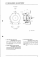
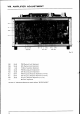
1.
GUIDE ROLLER
LOOSE
PLAY
ADJUSTMENT
(Refer
to
Fig.
8)
Adjust
the
stopper
(roller pulley
on
the
right)
screw
(d)
so
that the loose
play gap
is approximately
0.1 mm when the
guide
roller is moved as
indicated
by
arrow mark
in Fig.
8.
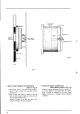
2. TENSION
MICRO
SWITCH
POSITION
ADJUSTMENT
(Refer
to Fig.
8)
Adjust the
screws
(e)
so
that the
gap
between
the
arm
cam and the
micro
switch is approximately 0.5 to
0.8 mm. Check
that
the micro switch works and that
the arm lock
smoothly
disengages.
Fig.8 Roller Block
3.
ROLLER
BLOCK
HEIGHT
ADJUSTMENT
(Refer
to
Fig.
8)
Use the U type
adjusting washers for screws
(u), (b),
and
(c)
to adjust
the
roller
block height: the distance
between
the
tape
guide
center
to the chassis board
should
be 43 mm.
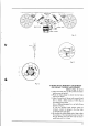
NOTE:
Steps
I and 3 also apply
to the right
guide
roller.
Z)