
User Guide

íÀ\
BRAKE
MICRO
,
''*'
swtTcH
\
o
55os
!5og
BRAKE
LEVER
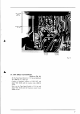
Fig.
12
ERAKE LEVER
Fig. I I
Fig. l3
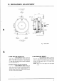
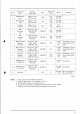
BRAKE BAND POSITION
ADJUSTI\{ENT
AND BRAKE
TENSION
ADJUSTMENT
(Refer
to Figs.
11 to 13)
1)
Adjust the
brake lever to
180"
position
by loosen-
ing the screws
(a)
and
(a').
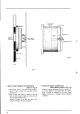
2)
Work the
brake
plunger
to check that the
brake
band is not slanted.
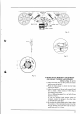
3) Adjust
the
position
of the
part
with screws
(b)
and
(b')
to obtain a brake tension
of 550
1
50g
on
both brakes at stop
mode.
(Use
a 10009 spring
gauge
for
a reel
with 60 mm
diameter
of tape.)
In
case
the
specified brake tension
cannot be
obtained, connect
the
springs to
the other
holes
on the brake lever
and adjust.
4) By working the brake plunger
with a finger,
adjust
the
position
of
the
microswitch
screw
(c)
so
that
the
gap
between the brake
lever and the
micro-
switch body
is
0.5
to
1.0
mm.
6.
E
€
IL
25