
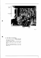
User Guide
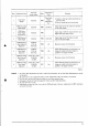
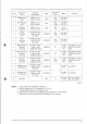

Step
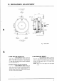
Adjustment
Item
Test
Tape
Supply Signal
Mode
Adjustment
Point
Result
Remarks
I
FWD Playback
Level
700H2
7-l
12
ips
OVU
Test Tape
FWD
VR3
50 kB
0t0.5dBm
(0.77sv)
2
REV
Playback
Level
7O0Hz7-112
ips
OVU
Test Tape
REV
VR4
s0 kB
010.5dBm
(0.77sv)
J
VU Meter
Sensitivity
700H27-l12
ips
OVU
Test Tape
FWD
VR5
lkB
OVU
indication
,
FWD
Recording
Level
Scotch
#2ll
Tape
1,000 Hz 0 dBm
Recording
F\ryD-REC
VR2
10
kB
0t0.5dBm
(0.77sv)
5
REV
Recording
Level
Scotch
#211
Tape
1,000
Hz 0 dBm
Recording
REV.REC
VRI
l0 kB
010.5dBm
(0.71sv)
6
FWD Frequency
Response
(3-3la
ips)
Scotch
#211
Tape
1.SkHz, 15kHz
-2OdBm
Recording
FWD-REC
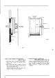
TC2
1.5 kHz,
l5
kHz
flat
Tape Speed
3-3l4
ips.
Recheck
Recording
Level.
1
REV
Frequency
Response
(3-3la
ip9
Scotch
#211
Tape
I
.5kHz,
l5kHz
-20dBm
Recording
REV.REC
TC1
1.5
kHz,
l5
kHz
flat
Tape Speed
3-3l4
ips.
Recheck
Recording
Level.
8
Frequency
Response
(7-112
ips)
Scotch
#2ll
Tape
1.5kHz,
l5kHz
-20dBm
Recording
FWD-REC
VR7
30
kB
1.5 kHz,
l5
kHz
flat
Tape
Speed
7
-112
ips.
Recheck
Recording
Level.
9
FWD Distortion
Confirmation
Scotch
#211
Tape
1,000H2
0 dBm
Recording
FWD-REC
Less
than
05%
See
NOTE 4
10
REV
Distortion
Confirmation
Scotch
#211
Tape
1,000
Hz, 0 dBm
Recording
REV-REC
Less than
0.s%
See
NOTE
4
1l
Bias
Filter
REC
L3
Less than
-30
dB
Mic, Line
Volume at
Max.
See
NOTE
5.
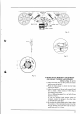
Chart-5
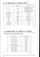
NOTES: 1.
2.
a
J.
A
ï.
5.
Output
Level Control
should
be at maximum.
Except for Steps
6 and 7, set Tape Speed
to 7-l12
ips.
Set
Tape Selector
Switch
to Low
Noise
position.
If it does not
comply with
the specifications,
repeat Steps
6 and 7,
and re-adjust.
Unless
the core
is moved
intentionally this adjustment
is
not
necessary.
31