Analog Filter Module
WARNING!! To reduce the risk of fire or electric shock, do not expose this apparatus to rain or moisture. 1-En CAUTION RISK OF ELECTRIC SHOCK DO NOT OPEN CAUTION: TO REDUCE THE RISK OF ELECTRIC SHOCK, DO NOT REMOVE COVER (OR BACK). NO USER-SERVICEABLE PARTS INSIDE. REFER SERVICING TO QUALIFIED SERVICE PERSONNEL. THE SYMBOLS ARE RULED BY UL STANDARDS (U.S.A.
WARNING WARNING: WHEN USING ELECTRIC PRODUCTS, BASIC PRECAUTIONS SHOULD ALWAYS BE FOLLOWED, INCLUDING THE FOLLOWING: WARNING The MFC42 is designed to be used in a standard household environment. Power requirements for electrical equipment differ from area to area. The operating voltage of this MFC42 is preset at the factory according to its intended destination. However, before connecting, check to see that the VOLTAGE SELECTOR on the rear panel is set to the correct voltage for your area.
WARNING For U.K. Customers Only WARNING THIS APPARATUS MUST BE EARTHED IMPORTANT This equipment is fitted with an approved non-rewireable UK mains plug. To change the fuse in this type of plug proceed as follows: 1) Remove the fuse cover and old fuse. 2) Fit a new fuse which should be a BS1362 5 Amp A.S.T.A or BSI approved type. 3) Refit the fuse cover.
WARNING FCC WARNING This equipment has been tested and found to comply with the limits for a Class B digital device pursuant to Part 15 of the FCC rules. These limits are designed to provide reasonable protection against harmful interference in a residential installation. This equipment generates, uses, and can radiate radio frequency energy and, if not installed and used in accordance with the instructions, may cause harmful interference to radio communications.
WARNING WARRANTY AKAI professional M.I. Corp. warrants its products, when purchased from an authorized “AKAI professional” dealer, to be free from defects in materials and workmanship for a period of 12 (twelve) months from the date of purchase. Warranty service is effective and available to the original purchase only, and only on completion and return of the AKAI professional Warranty Registration Card within 14 days of purchase.
WARNING v
CONTENTS CONTENTS Chapter 1 Introduction .................................................................................................... Features .................................................................................................................. Names and functions ............................................................................................... Front Panel .........................................................................................................
Chapter 1 Introduction Chapter 1 Introduction Thank you very much for your purchase of the MFC42. Here, you see its unique features and functions explained. Features Four 2-pole Analog Filters By the combination of four 2-pole filters, the MFC42 can be configured as 8-pole filter unit maximum. The sharp cut-off curve and powerful resonance setting allow wide range of sound making possible. Stereo and Mono Input Equipped with the Stereo Input and Mono Input independently and can be controlled separately.
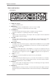
Chapter 1 Introduction Names and functions – Front Panel – 1. POWER switch button Switches the MFC42 on/off. 2. MIDI CH. key Sets the MIDI channel of the MFC42. Off, 01~16, L01~L16 (L: Local Off) 3. The value is indicated on 7-seg LED (key flickers while setting). CC NUMBER key To confirm the CC (Control Change) numbers assigned to the keys and knobs. The value is indicated on 7-seg LED (key flickers while confirming). 4. 5. +/– keys Adjust the value of various parameters.
Chapter 1 Introduction 12. A knob Sets the attack time of envelope. 13. D knob Sets the decay time of envelope. 14. S knob Sets the sustain level of envelope. 15. R knob Sets the release time of envelope. 16. ENVELOPE key The BEAT Module triggers the envelope for cut-off/resonance cyclically when it’s ON (key is lit while ON). 17. LFO key The BEAT Module applies the LFO of constant speed to cut-off/resonance when it’s ON (key is lit while ON). 18.
Chapter 1 Introduction 31. LEVEL knobs (Mono/Stereo channels) Adjusts the output level of filter module. These are used to balance the Mono/Stereo outputs. 32. LINK key Enables to control the cut-off for both Mono and Stereo channels simultaneously. The CUTOFF knob on Mono channel controls both channels. The CUTOFF knob on Stereo channel is disabled when LINK is ON (LED is lit while ON). 33.
Chapter 1 Introduction – Rear Panel – ` † @ · d Œ Æ ‰ Œ d ˝ h ~ A L r l b g ˝ J fl ¨ ¢ ¯ ” ‡ ¢ B ˝ ¤ ¢ ª ¢ ‰ ¢ ‰ X C † ¸ ” ‡ ¢ B 1. MONO IN 2. Input phone jack for the Mono channel. STEREO IN Two types of input connectors for the Stereo channels, 2 phone jacks and 2 RCA connectors. Both types of connectors can be used simultaneously (but without their balance control). When 3. Mono signal is used, connect it to L/MONO phone jack. LINE/PHONO switch 4.
Chapter 2 Basic Operation Chapter 2 Basic Operation Connections Be sure to turn all equipment off before making connections.
Chapter 2 Basic Operation Keywords in basic operation [Filter] As the coffee filter, it separates one to pass through and the other to block. In sound application, the Level separation is determined by their signal frequencies. This particular criterion frequency is called as “cut-off frequency”. There are several filter types of different characteristics.
Chapter 2 Basic Operation RESONANCE knob fully counter-clockwised position Level Cutoff frequency Level As the knob is turned up . . . Low Frequency High Low Frequency High [Pole] 2POLE (-12dB/oct) 4POLE (-24dB/oct) 8POLE (-48dB/oct) Determines the shape of cut-off curve. The larger the number, the sharper the curve. The sound character is different with different curves. (1 pole = -6dB/Octave) Note: Up to 8-pole is available on Mono channel.
Chapter 2 Basic Operation Changing the sound 1. Passing the filter First, pass the input signal through the filter on the Stereo channel. Press 2 POLE key on the Stereo channel. This makes the sound of rhythm machine go through the filter. You now hear the change in sound already. 2. CUTOFF change The CUTOFF knob changes the character of sound fed through the filter. Try rotating the CUTOFF knob, paying attention to the character of sound.
Chapter 3 Advanced Operations Chapter 3 Advanced Operations Keywords in advanced operation [LFO] The LFO stands for the Low Frequency Oscillator. The LFO waveform is used to control the pitch, level and character of sound cyclically. In the MFC42, the LFO is applied to the cut-off/resonance to change the character of sound cyclically. Also, the waveform of LFO changes the way it changes the sound character. Applying LFO to Cutoff/Resonance . . .
Chapter 3 Advanced Operations [ADSR] The ADSR stands for the Attack Changes time, Decay time, Sustain level and Release time of the envelope. In the Note OFF example of keyboard instrument, the Attack time is the time between the key press and the time it takes to reach the maximum sound level. Sustain level (S) The Decay time is the time it takes to reach reach to the sustain level Attack time Decay time (A) (D) from the maximum level.
Chapter 3 Advanced Operations Control the cut-off cyclically with Groove Modulator (TAP TEMPO) Cut-off control with LFO We’re going to explain how to control the cut-off by the Groove Modulator with the rhythm machine connected (stereo connection). Follow the steps below while playing back the rhythm machine. Preparation Turn on the LFO, CUTOFF and 2 POLE (Stereo channel) keys. Set the FILTER ON TYPE as LOW PASS and set the CUTOFF and RESONANCE knobs to 12 O’clock position.
Chapter 3 Advanced Operations In this set up, try changing the note length with the BEAT key or changing the LFO waveform with WAVE key. The way the sound changes is altered while still synced to the rhythm. Further, the rotation of CUTOFF and RESONANCE knobs and/or the selection of FILTER TYPE and the number of poles change the sound as well. The - 3 - key changes the selected note by the BEAT key to triplets. Cut-off control with Envelope Now, we’ll use the Envelope instead of LFO.
Chapter 3 Advanced Operations Up to this point, we explained how to control the cut-off using the LFO or Envelope. The same procedure can be applied to control the resonance by pressing the RESO key, instead of the CUTOFF key. When you want to control both the cut-off and resonance, turn both the CUTOFF and RESONANCE keys ON. Note: When both cut-off and resonance are controlled, it may sound as if the resonance is not changed since the cut-off effect is more dominant.
Chapter 3 Advanced Operations When receiving error occurred; • Check the cable connection. • Check the MIDI settings of the connected MIDI device. The rest of the procedure for the LFO waveform selection and its magnitude adjustment is the same as in Preparation for the TAP TEMPO settings (refer to page 12). The procedure to use the Envelope, instead of LFO, is similar. Difference • Press the ENVELOPE key, instead of the LFO key. • The BEAT key sets the trigger timing of Envelope, instead of LFO speed.
Chapter 3 Advanced Operations MANUAL TRIGGER What is Manual Trigger? The Manual Trigger is to control the cut-off/resonance by triggering the Envelope manually pressing the TRIGGER key at the desired point. The Manual Trigger triggers the Envelope only when the TRIGGER key is pressed, not like the Envelope being triggered cyclically by the Groove Modulator with the specified timing of BEAT module.
Chapter 3 Advanced Operations Invert function This function is used with Link function. It inverts the movement of cut-off control on the Mono and Stereo channels. In another word, when the CUTOFF knob on the Mono channel is rotated to one direction, the sound of Stereo channel changes sa if its CUTOFF knob is rotated to the other direction. Turn the LINK and INVERT keys on. Rotate the CUTOFF knob on the Mono channel. The sound of both the Mono and Stereo channels change simultaneously.
Chapter 4 MIDI Function Chapter 4 MIDI Function By connecting the external MIDI device (sequencer) via MIDI, the operation of keys/knobs and/or the settings of MFC42 can be controlled/recorded, other than the MIDI Clock Sync function described in Chapter 2. Refer to the Chapter 5 for the use of MPC2000/MPC2000XL. Most of keys and knobs on the MFC42 have the MIDI Control Change numbers assigned and their operations can be sent out as MIDI information.
Chapter 4 MIDI Function Sending the settings via MIDI The settings (of all keys and knobs) of the MFC42 can be sent out in one go via MIDI. This is called the Send Scene function. By connecting the MIDI sequencer, the settings can be recorded and recalled. Recording Set the MIDI channel of the recording track on the external sequencer and that of the MFC42 to the same channel. Next, start recording the sequencer. Then, press the + and - keys at the same time.
Chapter 5 Connections to Others Chapter 5 Connections to Others Connecting to Keyboard as external Filter Module The MFC42 can be used as the external filter module. As the MIDI note on message can trigger the Envelope by the MIDI Trigger function (Envelope is triggered by every note), the MFC42 can be used as the VCF module of the synthesizer. The A/D/S/R knobs adjust the shape of Envelope.
Chapter 5 Connections to Others MIDI Sync The connection via MIDI enables to sync the LFO speed/trigger timing of Envelope to the tempo of MPC2000/XL. MPC2000/XL setting Set the MPC2000/XL to Master mode in MIDI/SYNC mode to send out the sync signal to the MFC42. Press the [MIDI/SYNC] (9) key while holding the [SHIFT] key down to open the MIDI/SYNC screen. Set the [Mode] on its right to [MIDI CLOCK]. Sync Out (Out:A) .......................................................
Chapter 5 Connections to Others 3. Record the data on track Select the track16 to record and start playing back the MPC2000/XL. Move the CUTOFF knob (Mono channel) as the playback of Bass and Drum parts begin. The movement of CUTOFF knob will be recorded on the track16. 4. Playback the recorded data Press the [PLAY] key to playback the recorded data.
Chapter 5 Connections to Others MPC2000/XL Top of Song Bar 2 Bar 1 Track1 (Ch1) Play data Track10 (Ch10) Play data Track15 (Ch16) Setting data (Send Scene) Track16 (Ch16) Knob operation data MIDI IN MIDI OUT MIDI OUT MIDI IN MFC42 (16ch) When recording the settings and movement of keys and knobs on the MFC42 onto the sequencer, it is recommended to record the settings data and operation of keys and knobs onto the separate tracks.
Specifications Specifications Filter: LOW PASS, HIGH PASS, BAND PASS, NOTCH 2 POLE, 4 POLE, 8 POLE (Mono channel only) Effects: PHASE SHIFTER, DISTORTION Control: LFO WAVE (Triangle, Square, Sawtooth, Random), ENVELOPE GENERATOR (A, D, S, R), MIDI CLOCK SYNC (on/off) Knobs INPUT (x2), CUTOFF (x2), RESONANCE (x2), LEVEL (x2), PAN (Mono channel only), A, D, S, R, RATE, DEPTH, L-R PHASE, SPEED, DEPTH (PHASE SHIFTER), OUTPUT (DISTORTION), HIGH, LOW (EQ), MAIN VOLUME, PHONES LEVEL Keys 2 POLE (x2), 4 P
Printed in China