
User guide
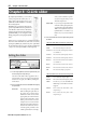
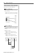
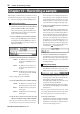
Table Of Contents
- warning_page.pdf
- MPC1000
- Table of contents
- Chapter 1 : Introduction
- Chapter 2 : Basic Operation
- Chapter 3 : Sequencer feature
- MAIN page
- Recording the performance
- Playing back a sequence
- Other useful features for recording sequences
- Detailed information on sequence feature
- Setting the length of a sequence
- Setting the time signature of the sequence
- Setting tempo
- Setting the loop for a sequence
- Changing the default settings
- Changing the sequence name
- Changing the default name for a sequence
- Copying a sequence
- Deleting a sequence
- Deleting all sequences
- Handling the duration (the length of a note) at the loop boundary
- Track features
- MIDI sequencer features
- Chapter 4 : Editing sequences
- Chapter 5 : Step editing
- Chapter 6 : Song mode
- Chapter 7 : Functions of a pad
- Chapter 8 : Q-Link slider
- Chapter 9 : Using the MPC1000 with external devices
- Chapter 10 : Recording a sample
- Chapter 11 : Editing a sample
- Chapter 12 : Program
- Creating a program
- Assigning/Reassigning samples to the pads
- Playing the sample while the pad is being hit
- Setting the volume and the tuning for a sample
- Changing the sample volume with velocity
- Playing several samples with one pad
- Switching between samples using velocity
- Setting the envelope for a pad
- The functions in the Program window
- Editing the sound of a sample
- Simulating the open/close hi-hat (setting the mute group)
- Setting the overlap of the sounds on the same pad (voice overlap)
- Delete all the unused samples at the same time (PURGE)
- Setting a MIDI note number to the pads
- Assigning MIDI note numbers to the pads (changing the default setting)
- Chapter 13 : Mixer
- Chapter 14 : Effect
- Chapter 15 : Save / Load
- Chapter 16 : Connecting the MPC1000 to your computer
- Chapter 17 : Other settings
- Appendix
MPC1000 v2 Operator’s Manual rev 1.0
44
Chapter 8: Q-Link slider
Chapter 8 : Q-Link slider
By using the Q-Link sliders, you can control
certain pad parameters (filter, tune, etc…)
with a slider or knob. There are two ways
(NOTE ON and REALTIME) for controlling
the sound by Q-Link.
NOTE ON, the sound will be affected to the
position of Q-LINK slider at the point the Pad
is hit. But the sound will not be affected by
changing the Q-Link sliders after hitting the
pad. REALTIME, you can change the sound
during playing back by changing the Q-LINK
slider.
In this section, you will learn how to set the Q-Link sliders.
This is done in the SLIDER mode, which can be accessed by
pressing the [MODE] key and then the [PAD 1] (SLIDER)
key. The SLIDER mode has 2 pages, [F1] (Q1) and [F2] (Q2)
, and you can set the Q-Link slider 1 and 2 separately.
Setting the slider
01. In the Assign pad field, select the pad to which you
wish to assign Q-Link by hitting it.
The effect of the slider will be applied to the se-
lected pad. If you do not wish to use the Q-Link
function for any pad, select OFF by turning the
DATA wheel.
02. In the Change field, select the condition for changing
the parameter.
NOTE ON : The setting value of the Q-LINK
slider at hitting the pad affects to
the sound. If you change the Q-
LINK slider while the sound is
playing back, the sound will not be
changed. The information of the
slider position will be sent to the
sampler section as Note Variation
data The Note Variation data is in-
cluded in the Pad Event and con-
verts the specific parameter value
to slider position data. For example,
when you select TUNE as a param-
eter, by moving the slider, you can
affect the sample tune.
REAL TIME :
If you change the Q-LINK slider
while the sound is playing backs, the
sound will be changed. When REAL
TIME is selected, the information of
Q-LINK slider is recorded as a Q-
LINK event , not as Note Variation
data.
03. In the Parameter field, select the parameter you wish
to control.
•
When the REAL TIME is selected in the Change field
TUNE : This controls the sample’s pitch.
LEVEL : This controls the sample’s volume level.
CUTOFF1+2 : This controls the cutoff frequency of both Fil-
ter 1 and Filter 2.
CUTOFF1 : This controls the cutoff frequency of Filter 1.
CUTOFF2 : This controls the cutoff frequency of Filter 2.
RESO1+2 : This controls the resonance value of both Fil-
ter 1 and Filter 2.
RESO1 : This controls the resonance value of Filter 1.
RESO2 : This controls the resonance value of Filter 2.
PAN : This control the sample’s pan position.
•
When the NOTE ON is selected in the Change field
TUNE :
This controls the sample’s pitch.
FILTER : This controls the cutoff frequency Filter.
LAYER :
This allows you to alter the HIGH and
LOW Range at which the Event will be
triggered.
ATTACK :
This controls the attack time of the
Amp Envelop.
DECAY :
This controls the decay time of the
Amp Envelope.