
User guide
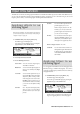
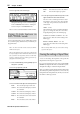

Table Of Contents
- warning_page.pdf
- MPC1000
- Table of contents
- Chapter 1 : Introduction
- Chapter 2 : Basic Operation
- Chapter 3 : Sequencer feature
- MAIN page
- Recording the performance
- Playing back a sequence
- Other useful features for recording sequences
- Detailed information on sequence feature
- Setting the length of a sequence
- Setting the time signature of the sequence
- Setting tempo
- Setting the loop for a sequence
- Changing the default settings
- Changing the sequence name
- Changing the default name for a sequence
- Copying a sequence
- Deleting a sequence
- Deleting all sequences
- Handling the duration (the length of a note) at the loop boundary
- Track features
- MIDI sequencer features
- Chapter 4 : Editing sequences
- Chapter 5 : Step editing
- Chapter 6 : Song mode
- Chapter 7 : Functions of a pad
- Chapter 8 : Q-Link slider
- Chapter 9 : Using the MPC1000 with external devices
- Chapter 10 : Recording a sample
- Chapter 11 : Editing a sample
- Chapter 12 : Program
- Creating a program
- Assigning/Reassigning samples to the pads
- Playing the sample while the pad is being hit
- Setting the volume and the tuning for a sample
- Changing the sample volume with velocity
- Playing several samples with one pad
- Switching between samples using velocity
- Setting the envelope for a pad
- The functions in the Program window
- Editing the sound of a sample
- Simulating the open/close hi-hat (setting the mute group)
- Setting the overlap of the sounds on the same pad (voice overlap)
- Delete all the unused samples at the same time (PURGE)
- Setting a MIDI note number to the pads
- Assigning MIDI note numbers to the pads (changing the default setting)
- Chapter 13 : Mixer
- Chapter 14 : Effect
- Chapter 15 : Save / Load
- Chapter 16 : Connecting the MPC1000 to your computer
- Chapter 17 : Other settings
- Appendix

MPC1000 V2 Operator’s Manual rev 1.0
82
Chapter 13: Mixer
02. In the Type field, select the filter type.
Setting set the filter type is same as in the Filter page
while in PROGRAM mode. Refer to “Editing the
sound of a sample” in the PROGRAM mode.
Note : You cannot use the Filter Modulation with INPUT THRU.
Using Q-Link feature in
INPUT THRU mode
You can control the input level, pan, and the filter’s param-
eter ( Cut-off frequency and Resonance) in real-time by us-
ing Q-Link slider.
Note : You cannot record the real-time control of the INPUT
THRU into the sequence.
Note : In this explanation, the necessary setting on the filter and
the input level/pan for INPUT THRU mode should be entered
first. If you haven’t set any parameter for them, set them while
referring to “Applying effects to an incoming signal” and “Ap-
plying filters to an incoming signal”
01. Select SLIDER mode by pressing [MODE] key then
hitting PAD 1 (SLIDER)
02. In the Assign pad field, select IN.
Note : Only “REALTIME” will be available in the Change field.
03. In the Parameter field, adjust the desired parameter.
LEVEL : This control the input signal volume level.
CUTOFF1+2 :
This controls the cutoff frequency of both Fil-
ter 1 and Filter 2.
CUTOFF1 : This controls the cutoff frequency of Filter 1.
CUTOFF2 : This controls the cutoff frequency of Filter 2.
RESO1+2 : This controls the resonance value of both Fil-
ter 1 and Filter 2.
RESO1 : This controls the resonance value of Filter 1.
RESO2 : This controls the resonance value of Filter 2.
PAN : This control the sample’s pan position.
04. In the High range field and Low range field, set the
upper and lower limit of the slider or knobs.
The value of the controlled parameter is deter-
mined by the value set here. The value depends
on the type of the parameter selected in the Pa-
rameter field.
LEVEL : 0 –100.
This is linked to the value in Level field in the INPUT
page. If you change the slider, the value will be
changed depending on the value in INPUT page.
CUTOFF1+2 / CUTOFF1 / CUTOFF 2
: -50 - +50
This value also offsets the current setting in the
INPUT page.
RESO1+2 / RESO1 / RESO2 : -50 - +50
Again, this value offsets the current setting in the
INPUT page.
Note : In the Input THRU mode, you cannot record the moving
of Q-Link in the sequence.
Saving the setting of Input Thru
You can save the setting of the Input Thru as the separate file
independent from the Program or Sequence file.
If you save the internal memory data using “SAVE ENTIRE
MEMORY”, the Input thru file will be saved with the Project file.
The Input Thru setting is contained in an Input Thru file.
When you load the Project file, the Input Thru file will be loaded
automatically along with the Project file. You can also load only
the Input Thru file. The Input Thru file ( .IPT file) is saved as the
file with IPT – and the project name.