User Guide WARNING To prevent fire or shock hazard, do not expose this appliance to rain or moisture.
Important Notice The material in this document is copyright to AKAI professional M.I. Corp., and may not be quoted or reproduced in any form without written permission from the company. LIMITED SOFTWARE WARRANTY POLICY All the software provided with, or purchased especially for, AKAI professional products has been tested for functionality. AKAI professional M.I. Corp. will make its best efforts to correct reported software defects for future releases subject to technical practicabilities.
WARNING: WHEN USING ELECTRIC PRODUCTS, BASIC PRECAUTIONS SHOULD ALWAYS BE FOLLOWED, INCLUDING THE FOLLOWING: WARNING The Z4/Z8 is designed to be used in a standard household environment. Power requirements for electrical equipment vary from area to area. Please ensure that your Z4/Z8 meets the power requirements in your area. If in doubt, consult a qualified electrician or AKAI professional dealer.
For U.K. customers only WARNING THIS APPARATUS MUST BE EARTHED IMPORTANT This equipment is fitted with an approved non-rewireable UK mains plug. To change the fuse in this type of plug proceed as follows: 1) Remove the fuse cover and old fuse. 2) Fit a new fuse which should be a BS1362 5 Amp A.S.T.A or BSI approved type. 3) Refit the fuse cover.
FCC WARNING This equipment has been tested and found to comply with the limits for a Class B digital device pursuant to Part 15 of the FCC rules. These limits are designed to provide reasonable protection against harmful interference in a residential installation. This equipment generates, uses, and can radiate radio frequency energy and, if not installed and used in accordance with the instructions, may cause harmful interference to radio communications.
Contents Contents 1 Parts and their functions . . . . . . . . . . . . . . . . . . . . . . . . . 1 Parts and their functions . . . . . . . . . . . . . . . . . . . . . . . . . . . . . . . . . . . 1 Top panel . . . . . . . . . . . . . . . . . . . . . . . . . . . . . . . . . . . . . . . . . . . . . . 1 Upper part of the top panel . . . . . . . . . . . . . . . . . . . . . . . . . . . . . . . . . . . . . Q-LINK section. . . . . . . . . . . . . . . . . . . . . . . . . . . . . . . . . . . . . . . . . . . . . .
Contents Editing a sequence . . . . . . . . . . . . . . . . . . . . . . . . . . . . . . . . . . . . . . . 36 Copying a sequence . . . . . . . . . . . . . . . . . . . . . . . . . . . . . . . . . . . . . . . . . . 36 Deleting a sequence . . . . . . . . . . . . . . . . . . . . . . . . . . . . . . . . . . . . . . . . . . 37 Viewing the parameters of all tracks . . . . . . . . . . . . . . . . . . . . . . . . . . . . . 37 Saving and loading a sequence . . . . . . . . . . . . . . . . . . . . . . . . . . . . .
Contents Saving and loading samples . . . . . . . . . . . . . . . . . . . . . . . . . . . . . . . 77 Saving samples . . . . . . . . . . . . . . . . . . . . . . . . . . . . . . . . . . . . . . . . . . . . . 77 Loading samples . . . . . . . . . . . . . . . . . . . . . . . . . . . . . . . . . . . . . . . . . . . . 79 9 Creating and editing programs . . . . . . . . . . . . . . . . . . 80 About programs . . . . . . . . . . . . . . . . . . . . . . . . . . . . . . . . . . . . . . . . 80 Creating a new program .
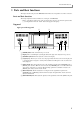
Parts and their functions 1 Parts and their functions This chapter describes the parts of the MPC4000 and their functions, and explains how to make connections. Parts and their functions This chapter explains the names and functions of each part of the MPC4000. * Names of panel knobs and keys and of the various jacks and connectors are printed in square brackets [ ] to distinguish them from the “virtual” buttons that appear in the display.
Chapter 1—Parts and their functions Q-LINK section You can assign internal MPC4000 parameters or MIDI messages to the knobs and sliders of this section, and control them in realtime. 1 2 A [SETUP] key: This key accesses the Q-LINK Setup page, where you can select the parameter that will be assigned to each knob and slider. 3 B [SEQUENCE] key: This key accesses the Q-LINK Sequence page, where you can record Q-LINK values and play them back automatically.
Top panel I [ERASE] key: This key is used to erase events from within a track. Events can be erased in realtime while overdubbing, or individual events can be erased while the sequencer is stopped. For details, refer to p.22, 24, 27. J [NOTE REPEAT] key: When you hold down this key and press one of the pads, the sound assigned to that pad will be triggered repeatedly. The interval of the repetitions can be adjusted in a range from an 8th note to a 64th note triplet.
Chapter 1—Parts and their functions D [TAP TEMPO] key: This key is used to manually specify the tempo. Striking this key repeatedly will automatically set the tempo to the corresponding quarter-note interval. E [WINDOW] key: This key opens a window for making detailed settings. When you move the cursor to a specific field in the display and press this key, a window for that field will open. Press this key once again to close the window.
Front panel F [MAIN OUT] jacks (phone): These are balanced main output jacks for connecting phone plug cables. They output the same signal as the [MAIN OUT] (XLR) jacks. G [MIDI IN I]/[MIDI IN II] connectors: These connectors receive MIDI messages. MIDI messages can be received independently at each connector. H [MIDI OUT A]–[MIDI OUT D] connectors: These connectors transmit MIDI messages. MIDI messages can be transmitted independently from each connector A–D.
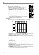
Chapter 1—Parts and their functions Audio/MIDI connections When connecting external audio or MIDI devices to the MPC4000, make connections as shown in the diagram below.
Connecting SCSI devices USB devices support “hot plugging,” which means you can connect or disconnect them even when the power is on. When you connect a USB device, the MPC4000 will recognize it automatically. Connecting SCSI devices The MPC4000’s rear panel has a [SCSI] connector that lets you connect devices such as a SCSI hard disk. Up to seven SCSI devices (including the MPC4000 itself) can be connected, and each device is distinguished by its own SCSI ID number.
Chapter 2—Introducing the MPC4000 2 Introducing the MPC4000 This chapter describes how the MPC4000 is structured, and explains the special terms you will need to know when using it. This chapter also explains the user interface of the MPC4000, and basic operating procedures. How the MPC4000 is structured Broadly speaking, the MPC4000 consists of the following three sections. • Sampler • Sequencer • Pads/controllers These sections internally communicate with each other using MIDI events (performance data).
Sampler section The following diagram is an example of a drum program in which one sample is assigned to each pad.
Chapter 2—Introducing the MPC4000 The following diagram also shows two key groups, each with four zones. However, the difference here is that the two key groups are crossfaded. KG1/ZN4: Samp 7 KG1/ZN3: Samp 5 KG1/ZN2: Samp 3 KG1/ZN1: Samp 1 KG2/ZN4: Samp 8 KG2/ZN3: Samp 6 KG2/ZN2: Samp 4 KG2/ZN1: Samp 2 • Multi A “multi” consists of performance settings for one or more programs that allow the program(s) to be played from the pads or sequencer.
Pad section Pad section Pads 1–16 The top panel contains sixteen velocity-sensitive pads. These pads are a user interface that corresponds to the keyboard of a synthesizer. However, the pads differ from a MIDI keyboard in that you can freely assign a note number to each pad. If you have selected a drum program, you can assign a different drum/percussion sound to each pad and play them. If you have selected a key group program, you can assign the necessary pitches to the pads to play a melody.
Chapter 2—Introducing the MPC4000 Accessing a page Each mode consists of multiple screens. Each of the screens in a mode is called a “page.” Each page is divided into blocks that contain related items, and each block contains one or more items that you can set. An area in which you can change the setting of an item is called a “field” Block Fields Operating the function keys Six function keys ([F1]–[F6] keys) are placed below the display in the top panel.
Editing a value 3. Use the CURSOR [π]/[†] keys to select the item that you want to set, and use the [JOG] dial to set the current date and time. 4. Press the [F6] key (SET). The popup window will close, and the specified date and time will be set for the internal clock. Note: The specified date and time will be used as the time stamp when saving a file. Hint: A popup window may also appear when you set the value of certain fields, or when you execute a function assigned to the [F1]–[F6] keys.
Chapter 2—Introducing the MPC4000 Hint: You are free to change the functions assigned to these keys. For details, refer to the PDF reference manual. • Using the Locate popup window If the MPC4000 is in a state in which you can play back a sequence, you can press the [GO TO] key to access a popup window where you can perform locate operations. IN this window you can memorize the current location as a locate point, or specify a locate point in measures/beats/ticks.
Editing a value 5. Press the [F5] key (SELECT). The contents of the storage device will be displayed as a tree in the file list block in the upper part of the screen. 6. Move the cursor to the View field in the center of the display, and use the [JOG] dial to select “PROGRAM.” In the View field you can select the type of files that will be displayed in the file list. If you choose PROGRAM, only program files will be displayed. 7.
Chapter 2—Introducing the MPC4000 9. Make sure that the Load field is set to WITH SAMPLES, and press the [F5] key (DO IT button). The MPC4000 will load the program. If the Load field is set to WITH SAMPLES, the necessary samples will be loaded into memory along with the program. The program has now been loaded into memory. In order to play the program, you will need to assign it to a part. 10. Press the mode section [MAIN] key. The main page will appear. Here you can create and play sequences. 11.
Creating and editing a sequence 3 Creating and editing a sequence This chapter explains how to record MIDI events into a sequence, and how to edit the recorded MIDI events. About sequences A “sequence” is the smallest unit from which an MPC4000 song is made up. You can specify the length (1–999 measures), tempo, and time signature of each sequence.
Chapter 3—Creating and editing a sequence Preparations for creating a sequence Before you can record MIDI events in a track, you must specify certain parameters such as the number of measures, the time signature, and the tempo. 1. Press the [MAIN] key. The main page will appear. Most of the steps involved in creating a sequence are performed in this page. Set the parameters of the sequence in the sequence block described below.
Realtime input The Change Bars popup window will appear. In this window you can specify the number of measures in the sequence. 4. Turn the [JOG] dial to specify the number of measures, and then press the [F6] key (DO IT) to finalize the setting. If you increased the setting, measures will be added after the current measure. If you decreased the setting, measures will be deleted from the end of the sequence. 5.
Chapter 3—Creating and editing a sequence 1. If you want to use a drum program of the internal sampler as your sound source, load the desired program into the internal memory of the MPC4000. 2. If you want to use an external rhythm machine as your sound source, connect one of the [MIDI OUT A]–[MIDI OUT D] connectors to the MIDI IN connector of your MIDI sound source. MIDI IN MIDI sound source 3. Press the [MAIN] key to access the main page.
Realtime input 5. Make sure that the Type field is set to DRUM. Hint: You can change this setting later as necessary. 6. Move the cursor to the Out1 field, and turn the [JOG] dial to select one of the following output destinations for the track. PART............... A specific part of the sampler section OUT A ............ [MIDI OUT A] connector OUT B ............ [MIDI OUT B] connector OUT C ............ [MIDI OUT C] connector OUT D ............ [MIDI OUT D] connector INT-A..............
Chapter 3—Creating and editing a sequence 11. To start recording, hold down the [REC] key and press the [PLAY] key. Then play the pads while you listen to the metronome. The [REC] key and [PLAY] key LEDs will light, and recording will begin on the currently selected track. Hint: If you press the [PLAY START] key instead of the [PLAY] key, recording will always start from the beginning of the sequence.
Realtime input 7. Move the cursor to the Out1 field, and turn the [JOG] dial to select the output destination for the track. 8. Move the cursor to the PART or Ch field, and turn the [JOG] dial to select the part number or MIDI channel. If you selected PART as the output destination, you can also select the program that will be played by that part (→p.14). 9. Strike the pads (or play your MIDI keyboard), and make sure that you can hear the program or MIDI sound source. 10.
Chapter 3—Creating and editing a sequence 15. To hear the content that you recorded, press the [PLAY] key (or the [PLAY START] key). 16. To erase a note event that you input by mistake, hold down the [OVER DUB] key and press the [PLAY] key. Then immediately before the note event that you want to erase, hold down the [ERASE] key and press the corresponding pad or note. If you erase the beginning (note-on) of a note event, that entire note event will be erased.
Realtime input 5. In the same way, move the cursor to the Out time field, and turn the [JOG] dial to set the punch-out point. The punch-out point is shown as a symbol on the position bar of the main page. 6. Press the [F1] key (CLOSE) to close the popup window. 7. Make sure that the cursor is located at the A.Punch field, and turn the [JOG] dial to change the setting to ON. This enables the auto punch-in/out function. 8.
Chapter 3—Creating and editing a sequence 5. Move the cursor to the Auto Step increment on key release field, and turn the [JOG] dial to make the field show YES. 6. Move the cursor to the Duration of recorded notes field, and turn the [JOG] dial to make the field show VALUE. If you select TC VALUE, the note value you specified in the Timing correct field will be input here. The numerical value at the right of the field indicates the proportion of the duration relative to the timing correct value.
Editing a track Editing a track The following pages explain how to edit the note events and continuously-variable events recorded in a track. Using the Graphic Editor to edit On the MPC4000 you can use a graphic display to visually edit note events and continuously-variable events such as control changes. Here’s how to use the graphic display to edit MIDI events. Editing a drum-type track You can use a graphic matrix editor to copy, delete, and modify the note events recorded in a drum type track. 1.
Chapter 3—Creating and editing a sequence • To select a single grid location Press the pad that corresponds to the note event you want to edit. The horizontal marker will move to the location for that pad. • To select multiple grid locations Press the pad that corresponds to the note event you want to edit, and hold down the [SHIFT] key and use the CURSOR [π]/[†]/[√]/[®] keys to extend the selected region. The grid locations where the vertical and horizontal markers intersect will be selected.
Editing a track A Move field: Indicates the direction in which the data will be moved. If this field is set to Time, the data can be moved along the time axis. If set to Note, the notes can be moved upward or downward. If the track is a drum-type track, this field can be set only to Time. B From field: Indicates the current position of the MIDI event(s) that will be moved. C to field: Specifies the location to which the data will be moved, in units of measures/beats/ticks.
Chapter 3—Creating and editing a sequence ■ [F5] key (EDIT)/(PASTE) The editing command assigned to the [F5] key will depend on whether you have selected a region in the graphic editor. EDIT will be assigned to this key if you have selected a region, and PASTE if you have not selected a region. • EDIT This command converts the MIDI events in the selected region. If this command is assigned to the [F5] key, the Edit Multiple popup window will appear when you press the key.
Editing a track Editing an INST type track You can use a piano-roll graphic editor to perform editing operations such as Copy or Delete on the note events recorded in an INST type track. 1. Select an INST type track in the main page, and press the [SEQ EDIT] key. When you select an INST type track and press the [SEQ EDIT] key, the piano-roll graphic editor will appear. A Track field: Selects the track that will be dis- 1 2 3 played in the graphic editor.
Chapter 3—Creating and editing a sequence • To select multiple notes Press the pad or MIDI key for one of the note events you want to edit. Then hold down the [SHIFT] key and use the CURSOR [π]/[†]/[√]/[®] keys to extend the selected range. The region in which the vertical and horizontal markers intersect will be the selected region. All note events whose beginning (note-on) is included in this region will be selected for editing. Hint: You can press the [F6] key (PLAY) to play back the selected region.
Editing a track 4. Move the cursor to the Timing correct field, and turn the [JOG] dial to specify the resolution of the time ruler. 5. Move the cursor to the Now field, and move the marker to the beginning of the area that you want to edit. 6. Use the BLOCK CURSOR [π]/[†] keys to move the cursor into the graph area. You can use the CURSOR [√]/[®] keys to move the marker in steps of the units shown on the time ruler. 7.
Chapter 3—Creating and editing a sequence 13. If desired, move the cursor to the Interval field and turn the [JOG] dial to specify the spacing at which the continuously-variable events will be added. You can set this field in a range of 1/4 (quarter note)–1 tick (1/960th of a quarter note). As you decrease the value of this setting, the continuously-variable events will change more smoothly. 14. Move the cursor to the Curve field, and turn the [JOG] dial to select one of the following curves.
Editing a track MIDI event type/continuously-variable event value (for other events) • System exclusive Each byte of the message (hexadecimal) 5. Turn the [JOG] dial to edit the value of the MIDI event. When editing a system exclusive, use the CURSOR [®] key to move to each byte. 6. If you want to edit the timing of an event, press the [F2] key (MOVE).
Chapter 3—Creating and editing a sequence Deleting a track Here’s how to delete a track from the sequence. 1. Access the main window and move the cursor to the Trk field. 2. Press the [WINDOW] key. The Track popup window will appear. 3. Press the [F4] key (DELETE). The Delete Track popup window will appear. A Delete track field: Selects the track to be 1 deleted. 4. Move the cursor to the Delete track field, and turn the [JOG] dial to select the track that you want to delete. 5.
Editing a sequence Hint: If you press the [F3] key (PARAMS) instead of the [F5] key (DO IT), only settings such as the sequence name and track parameters will be copied, and the MIDI events will not be copied. This is useful when you want to create two or more sequences with the same settings. Deleting a sequence Here’s how to delete a sequence in the memory of the MPC4000. 1. Access the main window, and move the cursor to the Seq field. 2. Press the [WINDOW] key. The Sequence popup window will appear. 3.
Chapter 3—Creating and editing a sequence F Chfield/Device field: Indicates the MIDI channel and device name to which each track is being output. This field will be displayed if OUT A–OUT D/INT-A/INT-B are selected as the output destination. G Part number/program field: Indicates the part number and program name to which each track is being output. This field will be displayed if PART is selected as the output destination.
Saving and loading a sequence A Disk information: Indicates the storage 2 device that is currently selected for the operation. B Type field: Selects the type of data that will be saved. 3 1 C Disk field: Selects the destination storage device. D Save to field: Indicates the folder within the destination storage device. E File list block: Displays the folder hierarchy within the selected storage device. 4 5 2.
Chapter 3—Creating and editing a sequence A saved All file will be indicated by an icon in the file list block of the Load page. Saving a single sequence Here’s how to save a single sequence from the memory of the MPC4000 to a storage device. 1. Press the [SAVE] key. The Save page will appear. 2. Move the cursor to the Type field, and turn the [JOG] dial to select SAVE SEQUENCE. When you select SAVE SEQUENCE, the following parts of the display will change.
Saving and loading a sequence A Disk information: Indicates the storage 2 device that you have selected for operations. B Disk field: Selects the load-source storage device. C File list block: Displays the hierarchy of the 1 contents of the storage device you selected. D View field: Selects the type of file that will be displayed in the file list block. E Wave free field: Indicates the amount of free memory within the MPC4000’s sampler section.
Chapter 3—Creating and editing a sequence • Move the cursor to the Seq field, and turn the [JOG] dial to select the desired sequence that you want to load from within the ALL file. • Move the cursor to the sequence list, and select the sequence number into which the sequence will be loaded. 7. To execute the load operation, press the [F5] key. When the data has been loaded, the contents of internal memory will be replaced by the contents of the file that was loaded.
Creating and editing a song 4 Creating and editing a song This chapter explains how to perform Song mode operations such as creating and editing a song. About songs A “song” consists of multiple sequences arranged in the order of playback. The MPC4000 lets you use 128 songs. Immediately after the power is turned on, all songs are blank. In order to use a song, you must choose one of these songs in which to perform your song-editing operations.
Chapter 4—Creating and editing a song When you modify the contents of a song, a song name of “Song_xxx” (x will be a song number 001–128) will be assigned automatically. 5. If you want the sequence you assigned in step 4 to be repeated, move the cursor to the Repeat field and turn the [JOG] dial to specify the number of repeats. Hint: You can also set the Repeats field to HOLD. In this case, that sequence will continue repeating until you press the [F6] key (NEXT) during playback. 6.
Editing a song If you copy or delete a step, the step you select here will be the step that is copied or deleted. If you insert or paste a step, the step will be inserted or pasted at the location of the step you select here. Hint: You can hold down the [SHIFT] key and use the CURSOR [π]/[†] keys to select multiple adjacent steps. 3. Use the [F3] key (COPY)–[F6] key (PASTE) to execute the desired editing operation. Each key has the following function. • [F3] key (COPY)..................
Chapter 4—Creating and editing a song Deleting a song Here’s how to delete a song from internal memory, returning it to an empty state. 1. Press the [SONG] key. The Song page will appear. 2. Move the cursor to the Song field, and turn the [JOG] dial to select the song that you want to delete. We recommend that you play back the song to make sure that it really is the song you intend to delete. 3. With the cursor located at the Song field, press the [WINDOW] key. The Song/Song Default field will appear.
Converting a song into a sequence The Convert Song to Seq popup window will appear. This popup window lets you convert a song into a sequence. 1 A From song field: Selects the song that will be converted. B To sequence field: Selects the destination for the converted sequence. 2 3 C Track status field: Selects how settings will be made for the tracks within the converted sequence. 4. Make sure that the song you want to convert into a sequence is selected in the From song field.
Chapter 5—Using multis and parts 5 Using multis and parts This chapter explains how to use “parts” which are the way you play the programs of the sampler section, and “multis” which let you manage multiple parts together. About parts In order to play a program that has been loaded into the sampler section, you must assign that program to a Part. You can think of a “part” as being the settings that a program need in order to play back; e.g., volume, pan, and output jack assignments.
Editing part parameters Editing part parameters The following pages explain how to select the program that will be used by each part, and set parameters such as volume, receive MIDI port and MIDI channel. Assigning a program to a part Here’s how you can assign a program from the MPC4000’s internal memory to each part of the currently selected multi. 1. Press the [MULTI] key, and then press the [F2] key (MIX). The Mix page will appear. In this page you can edit mix-related parameters for each part.
Chapter 5—Using multis and parts The setting of the parameter will change immediately when you adjust it. Each parameter has the following range. • Lvl (volume) field............................. –60.00 dB–+6.0 dB • Pan field ............................................ L50–MID (center)–R50 • Out (output destination) field ........... L/R ([MAIN OUT] jacks), 1–8 (optional individual outputs), 1/2, 3/4, 5/6, 7/8, L, R • FX (effect bus) field..........................
Adding or deleting a part 1 3 45 A Multi field: Indicates the name of the cur- 6 rently selected multi. B Part field: Indicates the part numbers. C Program/Type field: Selects the program 2 that will be assigned to the part. The Type field shows an abbreviation to indicate the program type. D Low field: Specifies the note number that will be the lowest note sounded by the part. E Hi field: Specifies the note number that will be the highest note sounded by the part.
Chapter 5—Using multis and parts 1 2 3 A Tag field: Move the cursor to this area and turn the [JOG] dial to switch the symbol on/off. Use this field when you want to specify more than one multi as the object of your operations. B Multi list: Lists the multis that are in internal memory. C MIDI Prog No. Indicates the multi change numbers that are assigned to the multis. D [F6] key (SORT): Displays the Sort popup window where you can rearrange the multis.
Copying a multi Copying a multi Here’s how to copy a multi within the internal memory of the MPC4000. 1. Press the [MULTI] key. The list page will appear. 2. Move the cursor to the multi list, and press the [WINDOW] key. The Multi popup window will appear. 3. Press the [F6] key (COPY). The Copy Multi popup window will appear. A Copy Source field: Selects the copy-source 1 multi. B New name field: Specifies a name for the 2 copied multi. 4.
Chapter 5—Using multis and parts Saving or loading a multi You can save or load multis/parts to or from a storage device. Saving a multi Here’s how to save a multi from internal memory to an internal or external storage device. Since all multis in internal memory will be lost when you turn off the power, you must use this procedure to save any multis that you want to keep. 1. Press the [SAVE] key. The Save page will appear.
Saving or loading a multi The Save a Multi popup window will appear, where you can execute the save operation. A Save field: Specifies how the programs and 1 2 samples included in the multi will be saved. B Replace same files field: Specifies how identically-named programs or samples existing in the save-destination will be handled. Hint: If the File Exists popup window appears when you press the [F5] key, an identically-named multi already exists on the storage device.
Chapter 5—Using multis and parts 2. Move the cursor to the Disk field, and turn the [JOG] dial to display the Disk List popup window. 3. Move the cursor to the storage device from which you want to load data, and press the [F5] key (SELECT). The storage device at the cursor will be selected as the loading-source. 4. Move the cursor to the View field, and turn the [JOG] dial to select the type of file that you want to load.
Mixer mode operations 6 Mixer mode operations This chapter explains how to use Mixer mode to adjust the mix parameters of the parts. About Mixer mode In Mixer mode you can use the part mixer to adjust the mix parameters of each part. The Part Mixer lets you adjust the volume, pan, and effect bus send level for each part within the currently selected multi. These parameters are in common with the parameters of the multi, and adjusting either will also affect the other one.
Chapter 6—Mixer mode operations 4. Use the [Q1]/[Q3] knobs and [Q5] slider of the Q-LINK section to adjust the mix parameters of the currently selected part. While the Part page is displayed, you can use the [Q1] knob, [Q3] knob, and [Q5] slider to adjust the Fx field, Pan field, and Level field of the currently selected part. Note: Q-LINK is temporarily turned off while the Part page is displayed. 5. Repeat steps 2–3 to adjust the mix parameters of each part. 6.
Effects 7 Effects • • • • The MPC4000 contains four effect units (effects 1–4) that you can use to process the programs of the sampler section. For each effect unit, you can select one of 52 effect types, and edit the effect parameters to obtain a wide range of effects. To use the effects, you will send the signal of each part to the effects via four effect buses (A–D) provided within the MPC4000. When the MPC4000 is in the default state, effects 1–4 are connected to Part 1 Effect 1 effect buses A–D.
Chapter 7—Effects 2. If you want to select an effect type, move the cursor to the Effect field of effects 1–4, and turn the [JOG] dial. The Select Effect Type popup window will appear. In this popup window you can select the effect type. A Effect list: Selects the effect type that will be 1 used. B [F1] key (CLOSE): Cancels the operation and closes the window. C [F3] [F6] key (SELECT): Finalizes the effect type you selected in 1. 2 3 3. Turn the [JOG] dial to select the effect type.
Basic effect operations 1 2 A Level field: Adjusts the signal level that is output from each effect. B Direct signal field: Selects whether the signal (unprocessed sound) from the parts that select the corresponding FX bus will be sent to the output jacks. If this is on, the signal from the part(s) and the signal processed by the effect will be mixed immediately before the output jacks.
Chapter 7—Effects 10. Repeat steps 1–6 to make settings for other effects in the same way. 11. Press the [MULTI] key, and then press the [F2] key (MIX). The Mix page will appear. In this page you can adjust the mix parameters of the parts that are included in the currently selected multi. For a detailed explanation of this page, refer to page 49. 12. Move the cursor to the Send field of the part to which you want to apply an effect, and select the effect bus to which the signal will be sent. 13.
Recording and editing samples 8 Recording and editing samples This chapter explains how you can record an external audio source (CD, record, vocal, etc.) connected to the MPC4000, and edit the sample so that you can use the Sampler section to play it. About samples A “sample” is one of the individual pieces of waveform data in memory from which the sounds of the Sampler section is constructed.
Chapter 8—Recording and editing samples Recording (sampling) an external source Here’s how you can record an external analog source connected to the REC IN [LINE/MIC] jacks or [PHONO] jacks, and add the sample to the currently selected program. Hint: In order to play a sample that you record, you must assign the sample to a program. In this example, we will show how to assign the sample to the program that is created in memory when you turn on the power of the MPC4000. Preparations before recording 1.
Recording (sampling) an external source Stop recording Start recording level Rec start threshold parameter time Time parameter Stop recording Start recording level Rec start threshold parameter • If you want to start recording manually Set the Record Start field to MANUAL. With this setting, recording will begin when you press the appropriate key. This method is convenient when you are recording a drum loop etc. from a CD or record. Start recording Stop recording level time 7.
Chapter 8—Recording and editing samples 9. Set the Pre-recording time field and the Bit field as necessary, and press the [WINDOW] key or the [F1] key (CLOSE) to return to the previous screen. For example if you have selected THRESHOLD as the Record start method, you can set the Pre-recording time field to several hundred milliseconds so that the attack portion of the waveform will not be omitted from the recording.
Making various settings for a sample you recorded A [F1] key (RETRY): Discards the sample. B [F3] key (PLAY): Auditions the sample. C [F5] key (ADD PGM): Retains the sample in memory, and adds it to the program. D [F6] key (KEEP): Retains the sample in memory. 1 2 3 4 3. Press the [F3] key (PLAY) to audition the sample. If you want to re-try the recording, press the [F1] key (RETRY). If you are satisfied with the sample, press the [F5] key (ADD PGM).
Chapter 8—Recording and editing samples The Sample mode Sample list page will appear. This page shows a list of the samples currently in memory. A Tag field B Sample field: Lists the names of the samples 3 2 currently in memory. Newly recorded samples and samples that were edited after being loaded or saved will have a * symbol displayed in front of their name. 1 The characters displayed at the right of the sample name have the following significance. ST ...........Stereo sample MN .........
Making various settings for a sample you recorded L [F1] key (LIST): Accesses the Sample List page. M [F2] key (TRIM/LP): Accesses the Trim/Loop page from another page. N [F3] key (REGION): Accesses the Region page. O [F4] key (Q-FX): Accesses the Q-FX page, where you can apply effects to the currently selected sample to create a new sample. P [F5] key (EDIT): Accesses the Sample Edit popup window, where you can edit the sample. Q [F6] key (P®ALL): Plays the entire sample once.
Chapter 8—Recording and editing samples To change the value of the start point, you can either turn the [JOG] dial, or use the numeric keys to directly input the number of samples and then press the [ENTER] key. Hint: By holding down the [SHIFT] key and pressing the CURSOR[√]/[®]keys, you can move the decimal place that will be modified by the [JOG] dial. It is convenient to start with a higher decimal place, and then move successively to lower decimal places as you make more precise adjustments. 7.
Applying Q-FX and resampling If you select COMMAND A Command field: Selects up to two commands with which to process the sample. 1 B Wet/Dry field: Adjusts the balance between 2 the sound processed by FX1–FX4 (Wet) and the original sound (Dry). C Effect field: Switches the effect on/off. D [F1] key (CANCEL): Halts the operation and returns to the previous page. 3 4 5 6 E [F3] key (®EFFECT): Auditions the sound processed by the effect. F [F4] key (®ORIGINAL): Auditions the original sample.
Chapter 8—Recording and editing samples A New name field: Displays the name of the sample. If necessary, you can move the cursor to this field and edit the name. 1 B [F1] key (RETRY): Discards the edited result, and returns to the previous page. C [F2] key (OVER WR): Overwrites the edited result onto the original sample in memory, replacing it. 2 3 4 5 6 7 D F3] key (P®ORIGIN): Plays the sample as it was before editing. E [F4] key (P®NEW): Plays the edited sample.
Dividing a sample 4. To execute the sample edit command, press the [F6] key (DO IT). The Keep or Retry popup window will appear, where you can compare the results of the command with the original data, and decide whether to keep the edited result. 5. Use the [F3] key (P®ORIGIN) and [F4] key (P®NEW) to compare the samples before and after editing. 6. If you are satisfied with the edited result, assign a new name to the sample as desired, and press the [F2] key, [F5] key, or [F6] key to save the new sample.
Chapter 8—Recording and editing samples J [F1] key (LIST): Accesses the Sample List page. K [F2] key (TRIM/LP): Accesses the Trim/Loop page. L [F3] key (REGION): Accesses the Region page from another page. M [F4] key (BPM): Accesses the BPM Match popup window, where you can adjust the length or pitch of a region according to a specified BPM value. N [F5] key (EDIT): Accesses the Sample Edit popup window, where you can edit the sample. O [F6] key (P®ALL): Plays the entire sample once. 2.
Dividing a sample 2. Move the cursor to the Region start field, and edit the region start point. To adjust the value, you can either turn the [JOG] dial, or use the numeric keys to directly input a number of samples and then press the [ENTER] key. Hint: By holding down the [SHIFT] key and using the CURSOR[√]/[®]keys, you can change the decimal place that is adjusted by the [JOG] dial.
Chapter 8—Recording and editing samples 7. Press the [F6] key (DO IT). The SLICE SAMPLE command will be executed, and a program of the same name as the selected sample will be created. Also, a track with the same name as the sample will be created in the selected sequence. Playing the track you created Here’s how the new track you created using the SLICE SAMPLE command can be used to play the newly created program. 1. Press the [MAIN] key to access the Main page. 2. Select the sequence and track.
Saving and loading samples TUNE The tempo of the phrase will be changed by changing the pitch of the sample. 2 A New tempo field: Specifies the desired result tempo. B Tune field: Indicates how much the pitch has been changed by the setting you made for the New tempo field. You can also change this value to adjust the New tempo. 2 STRETCH The tempo of the phrase will be adjusted using the Time Stretch function. 6. Move the cursor to the New tempo field, and specify the desired tempo.
Chapter 8—Recording and editing samples 2 3 A Tag field: In this field you can assign a tag to individual samples. Use this when you want to save all tagged samples in one operation. Move the cursor to this field, and turn the [JOG] dial to switch the tag on/off. 1 B Sample list field: Lists the names of the samples that are currently in memory. Newly recorded samples and samples that have been edited after they were last loaded or saved will be indicated by a * symbol in front of their name.
Saving and loading samples 11. According to the type of samples you are saving, press one of the following function keys. [F1] key (CANCEL) ..........Cancel the Save operation and close the popup window. [F3] key (TAGGED) ..........Save only the tagged samples and close the popup window. [F4] key (MODIFY) ..........Save only the samples marked by the * symbol and close the popup window. [F6] key (ALL) ..................Save all samples and close the popup window.
Chapter 9—Creating and editing programs 9 Creating and editing programs This chapter explains how to assign samples to a newly created program and edit the various sound parameters to create your own original program. About programs The units of sound handled by the Sampler section are called “programs.” A program consists of one or more samples (waveform data) together with sound parameters such as filter, envelope, and LFO. The MPC4000 has two types of program.
Assigning samples to a program 2 3 4 A Tag field: In this field you can assign a tag to individual programs. Use this when you want to save tagged programs in a single operation. B Program list field: Lists the names of the 1 programs currently in memory. Newly created programs and programs that you have edited after they were last loaded or saved will have a * symbol displayed in front of their name. C Program type field: Indicates the type (DRUM or KEY GROUP) of each program listed in 2.
Chapter 9—Creating and editing programs For details on how to record or load samples, refer to chapter 8. Hint: If you will be creating a key group program, we recommend that you connect a MIDI keyboard or similar controller to the [MIDI IN] connector so that you can audition the samples conveniently. 2. Press the [PROGRAM] key, and then press the [F1] key (LIST). The Program mode List page will appear. 3.
Assigning samples to a program 6. Move the cursor to the Number of new KGs field, and specify the number of key groups you want to add. If you created a new key group program, there will initially be only one key group. You will need to use this popup window to add the desired number of key groups. 7. Press the [F6] key (CREATE). The specified number of key groups will be added, and you will return to the Key Group Mix page. 8.
Chapter 9—Creating and editing programs Assigning samples to a drum program 1. Record the samples that you want to assign to the program. (You can either record new samples into memory, or load them from a storage device.) For details on how to record or load samples, refer to chapter 8. 2. Press the [PROGRAM] key, and then press the [F1] key (LIST). The Program mode List page will appear. 3.
Assigning samples to a program Level field: Sets the level of each note number. Pan field: Sets the pan (L50–MID–R50) if the note number is output in stereo. This has no effect if you are using monaural output. Out field: Sets the output destination jack for each note number. If you select MULTI, the output settings of the multi will be used. FX field: Indicates the send level of the signal that is sent from this note number to the effect bus.
Chapter 9—Creating and editing programs Note: Key group programs do not contain pad assign settings. Thus, the [F4] key function (Assign) will not be displayed if a key group program is selected in the List page. If you strike the pads when a key group program is selected, note data will be output according to the default pad assign settings (these are referred to as the “global pad assign” settings).
Editing sound parameters Decay field: Specifies the decay time of the envelope (the time from when the attack time ends until the sustain level is reached). Sustain field: Specifies the sustain level of the envelope (the level that will be maintained as long as you continue holding the key or pad). Release field: Specifies the release time of the envelope (the time from when the key is released until the level reaches zero).
Chapter 9—Creating and editing programs 6. To apply the filter envelope to the filter, press the [WINDOW] key when the cursor is located in the FILTER block. Note: Be aware that unlike the amp envelope, simply setting values for the filter envelope is not enough to produce an effect. In order to use the filter envelope, you must make settings in the Program Modulation popup window to specify the modulation source, modulation destination, and modulation depth.
Using zones Wave field: Selects the LFO waveform from TRIANGLE (triangle wave), SINE (sine wave), SQUARE (square wave), SAW UP (upward sawtooth wave), SAW DOWN (downward sawtooth wave), and RANDOM (random change). Depth field: Specifies the LFO output level. Rate field: Specifies the LFO frequency. Delay field: Specifies the time from when you press a key until the LFO is applied. Phase field: Adjusts the location at which the LFO cycle will begin.
Chapter 9—Creating and editing programs 2 5 67 8 A Note/Kg field: Selects the key group/note number that you will edit. B Edit field: Selects the editing method for the key group. 1 3 4 C Zone field: Indicates the zone numbers. D Sample field: Selects the sample that will be assigned to each zone. 9 K L M N O J Note: The sample that you select in the Key Group Mix page will always be assigned to zone 1 of the corresponding key group/pad number.
Other settings 9. Leave the cursor at the Range field, and press the [WINDOW] key. The Program Modulation popup window will appear. 10. Move the cursor to an empty Source field, and select VELOCITY as the modulation source. 11. Move the cursor to the Destination field at the right, and select ZONE SELECT as the modulation destination. 12. Move the cursor to the Depth field, and set the value to 100. 13. Press the [WINDOW] key. You will return to the Zone page.
Chapter 9—Creating and editing programs 1. Press the [SAVE] key. The Save page will appear. 2. Move the cursor to the Type field, and turn the [JOG] dial to select SAVE PROGRAMs. A display like the following will appear. 7 8 2 6 A Disk information: Indicates the storage device that is currently selected for operations. B Type field: Selects the type of data that will be saved. C Disk field: Selects the save-destination storage device.
Saving or loading programs 1 2 A Save field: Specifies whether only the program will be saved, or the samples and program will be saved. B Replace same samples field: Specifies what will occur if the save destination contains an identically-named sample file. 9. Move the cursor to the Save field, and select one of the following save methods. WITH SAMPLES PROGRAM ONLY: All samples used by that program will be saved along with the program. PROGRAM ONLY: Only the program will be saved.
Chapter 9—Creating and editing programs 2 3 A Disk information: Shows information on the storage device that is currently selected for operations. B Disk field: Selects the storage device from which the data will be loaded. C File list block: Displays the internal hierarchy of the selected storage device. 1 D View field: Selects the type of file that will be shown in the file list block. 4 E Wave free field: Indicates the amount of free memory for the MPC4000’s sampler section.
Using storage devices 10 Using storage devices This chapter explains operations for internal and external storage devices. The file structure of the MPC4000 The various types of data in the internal memory of the MPC4000 (sequences, songs, multis, samples, programs) can be saved as separate files on an internal or external storage device.
Chapter 10—Using storage devices If the Do field reads DELETE, you can delete a file from the storage device. If a different operation is selected, turn the [JOG] dial to select DELETE. 3 2 A Disk information: Displays various information on the storage device that is currently selected for operations. B Disk field: Selects the storage device that contains the file you want to delete. 1 C File list block: Displays the internal hierarchical structure of the storage device.
Formatting a storage device 4. Move the cursor to the File type field, and turn the [JOG] dial to select the type of file you want to find. 5. Press the [F6] key (FIND) to execute. When the search is completed, the Found Files popup window will appear, displaying the search results. A File list: Displays a list of the search results. B [F5] key (LOAD): Loads the selected file. 1 2 6. Use the CURSOR [π]/[†] keys to select the desired file from the search results, and press the [F5] key (LOAD).
Chapter 10—Using storage devices Note: When you format a device, any data that had been stored on that device will be lost forever. Perform this operation with care to avoid erasing any important files. The time required for formatting will depend on the size and type of the storage device. Large device such as hard disks may take a very long time to format.
Using Q-LINK 11 Using Q-LINK This chapter explains the Q-LINK function, which lets you use the knobs and sliders of the MPC4000 to control the internal sampler in realtime. About Q-LINK Q-LINK is a function that lets you use the four knobs and two sliders in the Q-LINK section of the panel to control the parameters of the internal sampler. For each knob/slider, you can select the type of event (internal sampler level, pan, filter cutoff, LFO rate etc.) that you want to control.
Chapter 11—Using Q-LINK The knobs and sliders have separate pages. As necessary, move between these pages by pressing the [F1] key (to set knobs) or the [F2] key (to set sliders). 1 1 2 2 3 4 5 3 4 5 6 7 6 7 A Multi field: Selects the multi for which you want to make Q-LINK settings. B PART/FX field: When you operate a knob/slider, this setting specifies whether the program assigned to a part of the multi will be controlled (PART) or an effect parameter will be controlled (FX).
Using Q-LINK sequence Note: If you select OFFSET, moving the knob/slider in the negative direction will have no effect if the existing setting is zero. Likewise, moving the knob/slider in the positive direction will have no effect if the existing setting is the maximum. 7. Move the cursor to the Range field, and turn the [JOG] dial to set the amount of change that can occur. The Range field specifies the minimum and maximum values that can be controlled by the knob or slider.
Chapter 11—Using Q-LINK 3. Move the cursor to the Step field, and turn the [JOG] dial to specify the length of each step. For example, setting this to 1/64 will produce extremely rapid change with four steps per 16th note. If you set this to 1/16, each step will correspond to a 16th note. When STEP=1/64 When STEP=1/16 4. In the setting field, move the cursor to the step of the knob or slider that you want to set, and move the knob or slider to specify the value for that step.
MIDI and synchronization operations 12 MIDI and synchronization operations This chapter explains how to make MIDI-related settings, and how to synchronize the MPC4000 with an external device. MIDI event transmission and reception The sequencer, sampler, and pad sections of the MPC4000 use MIDI events to communicate internally.
Chapter 12—MIDI and synchronization operations If you select INT-A/INT-B MIDI events will be sent through the internal virtual MIDI port to the various parts. In this case, you will need to set the MIDI transmit channel of the pads or your MIDI keyboard to match the MIDI receive channel of the part you want to play. If you select SEQUENCER (default setting) MIDI events will be sent to the tracks of the sequencer.
Synchronized operation with other devices The MIDI mode Event page will appear. 1 2 3 A MIDI monitor field: Selects the MIDI connector that you will monitor. B View channel field: Selects the MIDI channel that you will monitor. C Monitor field: Displays the MIDI events that are being transmitted or received. 2. Move the cursor to the MIDI monitor field, and turn the [JOG] dial to select the MIDI connector whose MIDI events you want to view as a list. 3.
Chapter 12—MIDI and synchronization operations 3. Move the cursor to the Mode field, and turn the [JOG] dial to select one of the following as the synchronization signal that the MPC4000 will receive. The display will change according to the synchronization signal you select. ■ MIDI CLOCK MIDI Clock will be used for synchronization. A Sync in field: Selects the connector at which 1 MIDI Clock will be received. ■ MIDI TIME CODE MTC (MIDI Time Code) will be used for synchronization.
Synchronized operation with other devices 11. Begin playback on the external device. The MPC4000 will start playing the currently selected sequence or song in synchronization with the external device. When you perform play/stop/locate operations on the external device, the MPC4000 will follow. Hint: If the Receive MMC field is on, an MMC-compatible external device can transmit MMC commands to the MPC4000 to operate its transport.
Chapter 12—MIDI and synchronization operations 9. Make settings on the external device so that it will synchronize to the synchronization signal you selected in steps 3–5, and put it in playback-ready mode. 10. If you want the external device to synchronize to an MPC4000 sequence, go to the main page and select the sequence that you want to play. 11. If you want the external device to synchronize to an MPC4000 song, press the [SONG] key, and then select the song that you want to play. 12.
Specifications General Sound Generator Power supply 100–240V AC 50/60Hz 70W (27W without options) Dimensions 526 (W) × 170 (H) × 453 (D) mm (with LCD tilted down) Weight 10.5kg (without options) Display 320 × 240 dots grey-scale graphical LCD w/back light Sampling rate 44.1kHz, 48kHz, 96kHz Data format 24/16 bit linear Sampling time (unexpanded memory) 180/120 (16/24 bit) seconds mono FS=44.
MPC4000 MIDI IMPLEMENTATION CHART (Sequencer section) Version : V1.0 Date : March 2002 FUNCTION...
MPC4000 MIDI IMPLEMENTATION CHART (Sound generator section) Version : V1.0 Date : March, 2002 FUNCTION...