
User Guide


Parts and their functions
1
1 Parts and their functions
This chapter describes the parts of the MPC4000 and their functions, and explains how to make connections.
Parts and their functions
This chapter explains the names and functions of each part of the MPC4000.
* Names of panel knobs and keys and of the various jacks and connectors are printed in square brackets
[ ] to distinguish them from the “virtual” buttons that appear in the display.
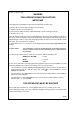
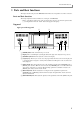
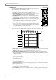
Top panel
Upper part of the top panel
A [POWER] button: This switch turns the power on/off.
B Display: This is a backlit liquid crystal display (LCD). The angle can be adjusted in five positions.
C [CONTRAST] knob: This knob adjusts the contrast of the display.
D [F1]–[F6] keys: These keys are used to access the pages indicated in the bottom row of the display, and
to execute the function assigned to each key. The actual function will depend on the screen that is cur-
rently displayed.
E [GAIN] switch: This switch selects the gain of the signal that is input from the [LINE/MIC] jacks or
[PHONO] jacks. Set this to HI if mics are connected to the [LINE/MIC] jacks, or to LOW if a line-level
device such as a CD player is connected. When inputting signals from a turntable connected to the
[PHONO] jacks, always set this switch to LOW.
F [REC GAIN] knob: This knob adjusts the recording level of the signal that is input from the
[LINE/MIC] jacks or [PHONO] jacks. The inner knob adjusts the right channel, and the outer knob
adjusts the left channel.
G
[MAIN VOLUME] knob: This adjusts the output level of the signal that is sent from the [MAIN OUT] jacks.
4
32
5 6 71