SERVICE MANUAL Model: PDP Safety Precaution Technical Specifications Block Diagram Circuit Diagram Basic Operations & Circuit Description Main IC Specifications Product Specification of PDP Module Trouble Shooting Manual of PDP Module Spare Part List Exploded View If you forget your V-Chip Password Software Upgrade This manual is the latest at the time of printing, and does not include the modification which may be made after the printing, by the constant improvement of product.
Safety Precaution CAUTION RISK OF ELECTRIC SHOCK DO NOT OPEN CAUTION: TO REDUCE THE RISK OF ELECTRIC SHOCK, DO NOT REMOVE COVER (OR BACK). NO USER-SERVICEABLE PARTS INSIDE. REFER SERVICING TO QUALIFIED SERVICE PERSONNEL ONLY. PRECAUTIONS DURING SERVICING 1. In addition to safety, other parts and assemblies are specified for conformance with such regulations as those applying to spurious radiation. These must also be replaced only with specified replacements.
5. When replacing a MAIN PCB in the cabinet, always be certain that all protective are installed properly such as control knobs, adjustment covers or shields, barriers, isolation resistor networks etc. 6. When servicing is required, observe the original lead dressing. Extra precaution should be given to assure correct lead dressing in the high voltage area. PRODUCT SAFETY NOTICE Many electrical and mechanical parts in this apparatus have special safety-related characteristics.
MODEL : Technical Specifications DATE FIRST ISSUED ISSUE PDP4206EM 42” Plasma Monitor RAISED BY CHECKED BY NUMBER OF PAGES 1 REVISIONS ISSUED DATE 9 DESCRIPTION SPECIFICATION AGREED : RAISED BY : SIGNATURE DATE ...................................................................................... ...... ........................... ... ...................................................................................... ...... ........................... ... Q/A DEPARTMENT .............
Technical 1. CONTINUATION PAGE Specifications PDP420 NUMBER 2 OF 9 PAGES Standard Test Conditions All tests shall be performed under the following conditions, unless otherwise specified. 1.1 Ambient light : 150ux (When measuring IB, the ambient luminance ≦0.1Cd/m2) 1.2 Viewing distance : 50cm in front of PDP 1.3 Warm up time : 30 minutes 1.4 PDP Panel facing : no restricted 1.
Technical CONTINUATION PAGE Specifications PDP4206EM NUMBER 3 OF 9 PAGES ELECTRICAL CHARACTERISTICS 2. 3. Power Input 2.1 Voltage : 110 ~120VAC 2.2 Input Current : 3.5 / 1.5A 2.3 Maximum Inrush Current Test condition : : <30 A (FOR AC110V ONLY) Measured when switched off for at least 20 mins 2.4 Frequency : 50Hz to 60Hz(±3Hz) 2.5 Power Consumption Test condition : : ≤ 330W full white display with maximum brightness and contrast 2.6 Power Factor : Meets IEC1000-3-2 2.
Technical 4.2 4.3 4.4 5. 6. PDP4206EM Audio input Audio I/P(L/Rx5) : 1 for DVI / D-Sub 1 for Y/ Pb/Pr 1 for Y/ Cb/Cr 1 for Video 1 for S-Video Audio output Audio O/P(L/Rx1) : 1 for Line out Other function : PIP, 16:9, 4:3, Zoom Environment 5.1 Operating environment 5.1.1 Temperature : 5.1.2 Relative humidity: 5.2 CONTINUATION PAGE Specifications Storage and Transport 5.2.1 Temperature : 5.2.
Technical CONTINUATION PAGE Specifications 6.11 Color temperature : PDP4206EM NUMBER 5 OF 9 PAGES Contrast at center (50); Brightness center (50); Color temperature set at Natural x=0.285±0.02 y=0.293±0.02 6.12 Cell Defect Specifications Subject to Panel supplier specification as appends. 7. Front Panel Control Button SEL. UP/Down Button : Push the key to selecting the item on OSD menu Volume Up/ Down Button : Menu Button : Push the key to increase the volume up or down.
Technical 9. Specifications CONTINUATION PAGE PDP4294LV1 NUMBER 6 OF 9 PAGES Agency Approvals Safety UL60950 Emissions FCC class B 10. Reliability 11.1 MTBF 11. Accessories : 20,000 hours(Use moving picture signal at 25°C ambient) : User manual x1, Remote control x1, Stand x1, Power cord x1, Battery x 2, Accessories box x 1.
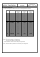
Technical CONTINUATION PAGE Specifications PDP4206EM NUMBER 7 OF 12. Supportthe Signal Mode The PDP can support the different from DVI or VGA Signal Mode in 24 kinds NO.
Technical 13. Specifications CONTINUATION PAGE PDP4206EM NUMBER 8 Remote Function+ Mute YPbPr PC C/C VOL +/Menu Left/Right Up/Down Left/Right Button SRS ZOOM plus/minus Display Sleep Standby on/off PIP Video Number Buttons/ Channel up/ Channel down/ Return V-CHIP I. P. C I. S. C EXIT Button Input BBE Wide Freeze F.
Technical Specifications CONTINUATION PAGE PDP4206EM NUMBER 9 OF 9 PAGES PHYSICAL CHARACTERISTICS 14. Power Cord Length : 1.8m nominal Type : optional : “Black” colour as defined by colour plaque reference number 15. Cabinet 15.1 Color 15.2 Weight (with stand) Net weight : 84.5lbs (38.3kg) 15.
Block Diagram Product Specification of PDP Module LVDS Input Control Signal (Serial Interface) Input Interface Controller Vs(180V~190V) Memory Controller Va(55V~65V) Vcc(+5V) Driver Timing Controller APL Data Color Plasma Display Panel 852 X 480 pixels Common sustain driver Scan Driver Display data, Driver timing Address Driver ☞ Applied Voltage level is specified at the time when Full-White pattern is displayed on the panel.
Block Diagram
Circuit Diagram - Power supply board of PDP Module, DGP-420WXGA Power supply board of PDP Module, USP490M-42LP Main (Video) board Audio/Tuner board Keypad board Remote control receiver board External L/R Speakers board Remote control board
5 4 CN01 3-176976-2 2 1 L104 CH108200S L103 CH108200S R108 5W 15 R103 5W 20 T208 PFC COIL 200uH D102 FEP30JP PFC + PFC+ 190VS CN03 3-176976-1 C101 275VAC 1uF RELAY1 SDT-SH-118DM TNR101 14D 621K Q102,Q103,Q109 SPW20N60C3*3 R603 BD101 D25XB60 R112 R224 2.2M PFC VCC R115 1.5KF R109 1W 4.7 3K C108 680pF R106 1W 4.7 R107 1W 4.7 R116 10KF D213 LL4148 R130 240KF C114 0.68uF R133 33KF R114 R132 33KF C115 3 EN 10 C220 RYC D104 US1M R142 6.8KF R141 4.7KF Q207 KRC103M 8 0.
USP490M-42LP
5 4 INPUT 2 AFE DVI GBAIN GGAIN RXCm RX0m GHSYNC RX1m RXCp HDCBIN HDYIN RX1p RX2p GRAIN Y RX0p RX2m GVSYNC CB HDCRIN CR D 3 RXCm RX0m RX1p RX1m RX0p GDFEOE RX2m RX2p RXCp HDCBIN HDYIN GAFEOE VGASEL GVSYNC GCOAST HDCRIN GRAIN SCL GBAIN GBLKSPL GGAIN SDA GHSYNC GRE[7:0] GPEN GBE[7:0] GVS GBO[7:0] GFBK GHS GGE[7:0] GCLK GRO[7:0] GGO[7:0] GBE[7:0] GRE[7:0] GHS GCLK GFBK GGE[7:0] GVS 04_AFE 03_DVI 02_INPUT MEMORY C VCP3230 VVINT CB RESETn Y SDA CR STBLED VUV[7:0] VVHS VY[7:0] VVCLK SCL VVVS VFIE
AVDD AVDD AVDD VCC C34 C35 C36 C37 C38 C39 C40 C41 C42 C43 0.1uF 0.1uF 0.1uF 0.1uF 0.1uF 0.1uF 0.1uF 0.1uF 0.1uF 0.1uF U5 LM2937_SOT223 1 0.1uF V33 V33 V33 V33 V33 V33 VCC U6 LM2937_SOT223 1 C45 C46 C47 0.1uF 47uF 0.1uF VI VO AVDD 3 C48 C49 0.1uF 47uF D V33 C50 C51 C52 C53 C54 C55 C56 C57 C58 0.1uF 0.1uF 0.1uF 0.1uF 0.1uF 0.1uF 0.1uF 0.
PVCC AVCC VCC U3 LM2937_SOT223 R15 510 SIRES C 96 EXT_RES RX0p RX0m 90 91 RX0p RX0m RX1p RX1m 85 86 RX1p RX1m RX2p RX2m 80 81 RX2p RX2m RXCp RXCm 93 94 RXCp RXCm SII161 U4 OVCC 100 4 1 7 3 9 2 99 GDFEOE OCK_INV PIXS DFO STAG_OUT ST PDO PD RSVD AGND1 AGND2 AGND3 AGND4 AGND5 PGND 8 SISCDT QE0 QE1 QE2 QE3 QE4 QE5 QE6 QE7 QE8 QE9 QE10 QE11 QE12 QE13 QE14 QE15 QE16 QE17 QE18 QE19 QE20 QE21 QE22 QE23 10 11 12 13 14 15 16 17 20 21 22 23 24 25 26 27 30 31 32 33 34 35 36 37 SIBE0 SIBE1
5 4 3 2 1 D[15:0] JP1 VPPEN 1 3 FWPn 2 4 A1 A2 A3 A4 A5 A6 A7 A8 A9 A10 A11 A12 A13 A14 A15 A16 A17 A18 A19 HDR_2X2 25 24 23 22 21 20 19 18 8 7 6 5 4 3 2 1 48 17 16 A0 A1 A2 A3 A4 A5 A6 A7 A8 A9 A10 A11 A12 A13 A14 A15 A16 A17 A18 VPP VCC 37 D1 D2 D3 D4 D5 D6 D7 D8 D9 D10 D11 D12 D13 D14 D15 D16 29 31 33 35 38 40 42 44 30 32 34 36 39 41 43 45 GND1 GND2 46 27 VPP C167 D0 D1 D2 D3 D4 D5 D6 D7 D8 D9 D10 D11 D12 D13 D14 D15 R69 R70 R71 3.3K 3.3K 3.
5 4 3 2 HDCR L1 FB_40_OHM_500MA HDCRF L2 FB_40_OHM_500MA L3 FB_40_OHM_500MA HDYF L4 FB_40_OHM_500MA L5 FB_40_OHM_500MA HDCBF L6 FB_40_OHM_500MA 1 HDCRIN J1 CR 8 R1 R2 R3 75 75 75 3 C1 Y 9 D1 28 0.
5 4 3 2 1 SDA SCL DBE[7:0] 47R 47R 47R C277 0.1uF 0.1uF 0.1uF 0.1uF 0.
4 3 2 1 V33 LED V33 13 ICSCLK ICSDAT ICSSTM D VDD 3 CLK1 11 CLK2 6 GND 5 OE 8 12 9 SCLK DATA STROBE 1 16 X1 X2 MCKEXT1 47 RMCK ICSREF V33 ICSSTD IX1 IX2 Y3 13 OE 8 12 9 SCLK DATA STROBE 1 16 X1 X2 VDD 3 CLK1 11 CLK2 6 GND 5 MCKEXT C232 D19 V33 C231 0.1uF 0.1uF 47 +5VIN R102 V33 DCKEXT NMI1 1 R106 ICS307 4 R107 SW1 SW_MOM_4P 2 1 2 3 4 0.1uF V33 VDD 8 RESET 6 RESET 5 SENSE RSTINn 2 RESIN TLCCT 3 CT 1 CONTROL C234 R389 0.
5 4 3 U12 C125 0.1uF 0.1uF C126 0.1uF C127 0.1uF C128 0.1uF C129 0.1uF MA9 MA10 19 BA LDQM UDQM DQM0 14 36 CLK_M 35 34 CLK CKE MWECASRASMCS- 15 16 17 18 WE CAS RAS CS 1 25 VDD VDD 7 13 38 44 VDDQ VDDQ VDDQ VDDQ V33N V33N C140 0.1uF C141 0.1uF C142 0.1uF C143 0.1uF C144 0.1uF C145 0.1uF C146 0.1uF C147 0.
5 4 U27 LM317S C251 0.1uF + 0.1uF 1 + C250 22uF 1 C253 VO TAB 1 D VI ADJ 3 2 1 V25 4 VCC 3 2 R126 510 D C252 22uF 2 2 C254 V25ADJ 1000uF-16V R129 510 +5VIN VCC C 1 C + 2 C259 220uF-16V VCC V33 C267 0.1uF C269 0.1uF 1 ADJ U29 LM3940IS-3.3 3 VI VO 2 + C268 22uF B 2 1 B C261 0.1uF C262 1000pF 上海家影多媒体技术有限公司 Shanghai Jiaying Multimedia Technology Co.
5 4 3 GFBK GGE[7:0] GBE[7:0] C GRO[7:0] GGO[7:0] GBO[7:0] B U26 V24 V23 V25 V26 W25 W24 W23 GGE0 GGE1 GGE2 GGE3 GGE4 GGE5 GGE6 GGE7 H23 G26 H25 P23 P24 P25 P26 R23 GBE0 GBE1 GBE2 GBE3 GBE4 GBE5 GBE6 GBE7 B25 A26 D24 E23 C25 B26 C26 E24 GBE0 GBE1 GBE2 GBE3 GBE4 GBE5 GBE6 GBE7 GRO0 GRO1 GRO2 GRO3 GRO4 GRO5 GRO6 GRO7 R24 R25 R26 T23 T24 T25 T26 U25 GRO0 GRO1 GRO2 GRO3 GRO4 GRO5 GRO6 GRO7 F23 D25 D26 F24 E25 E26 F25 F26 GGO0 GGO1 GGO2 GGO3 GGO4 GGO5 GGO6 GGO7 GBO0 GBO1 GBO2 GBO3 GBO4 GBO5 G
5 4 3 2 1 V33L L31 C207 330pF D DRE[7:0] DGE[7:0] DBE[7:0] DRO[7:0] DRO0 DRO1 DRO2 DRO3 DRO4 DRO5 DRO6 DRO7 DGO0 DGO1 DGO2 DGO3 DGO4 DGO5 DGO6 DGO7 DBO0 DBO1 DBO2 DBO3 DBO4 DBO5 DBO6 DBO7 V33L C R92 DGO[7:0] R94 10K NC R95 R96 NU 10K DRE0 DRE1 DRE2 DRE3 DRE4 DRE5 DRE6 DRE7 DGE0 DGE1 DGE2 DGE3 DGE4 DGE5 DGE6 DGE7 DBE0 DBE1 DBE2 DBE3 DBE4 DBE5 DBE6 DBE7 DBO[7:0] DCLK DENG DHS DVS B C208 330pF C210 330pF U20 LM2937_SOT223 0.
4 3 R17 VCCV 3.3K VVINT VCCV C280 U10 CCV2 R22 R25 C69 NC 33 R30 470 0.1uF 10 560pF 4 6 1 R32 VCCV VDD 12 BOX 17 R20 8.2K VIN INTRO RED HIN GREEN BLUE VIDED CSYNC REF LPF SEN SMS ASEL VSSA 18 2 3 R23 R26 R28 13K 13K 13K 10K C74 C75 47uF 0.1uF VCC R18 22K VCCR Q1 R19 22K VCCG SDA 2 S D SDA5V 3 D VCCB 8 SN7002 9 C286 R31 11 C287 6.8K Z86229 C71 C72 C73 6.8nF 68nF 0.
5 4 3 02_INPUT OUTA OUTB AUDIO OUTL AUDIO OUTB SIF SDA5V SCL5V SDA D C 2 1 03_AUDIO IR MUTE MUTE1 POWER_ON SCL SIF SCL5V SDA5V AUDIO OUTL AUDIO OUTR D C 02_INPUT 03_AUDIO 04_MCU+AMP POWER_ON RELAY MUTE OUTA OUTB MUTE1 IR B B 04_MCU+AMP A A 5 4 3 2 1
"U3(UVS7305M.
Audio/Tuner
"U8(TDA9850) only for the Model with Turner" Audio/Tuner
Keypad Remote control receiver External L/R Speakers
Remote control
Basic Operations & Circuit Description MODULE There are 1 pc. panel and 8 pc.s PCB including 2 pc.s Y/Z Sustainer board, 2 pc.s Y Drive board, 2 pc.s X (left and right) Extension PCB, 1 pc. Control (Signal Input) and 1 pc. Power board in the Module. SET There are 5 pc.s PCBs including 1 pc. Tuner/Audio board, 1 pc. Keypad board, 1 pc. Remote Control Receiver board, 1 pc. L/R Speakers and 1 pc. Main (Video) board in the SET.
Parts position Internal Speaker (Right) Power Supply Internal Speaker (Left) Y-Drive Top Z-Sustainer Y-Sustainer External Speaker Terminals Y-Drive Bottom Power SW X left Extension EMI filter + AC Inlet only for the Model with Turner Remote control Receiver Local key Main (Video) Stand Tuner/Audio Control (Signal Input) X right Extension
PCB function 1. Power: (1). Input voltage: AC 110V~240V, 47Hz~63Hz. Input range: AC 90V(Min)~265V(Max) auto regulation. (2). To provide power for PCBs. 2. Main (Video InterFace) board: To converter TV signals, S signals, AV signals, Y Pb/ Cb Pr/Cr signals, DVI signals and D-SUB signals to digital ones and to transmit to Control board. 3. Control board: Dealing with the digital signal for output to panel. 4. Y-Sustainer / Z-Sustainer board: (1). Receiving the signals from Control and high voltage supply.
PCB failure analysis 1. CONTROL: a. Abnormal noise on screen. b. No picture. 2. MAIN (VIDEO): a. Lacking color, Bad color scale. b. No voice. c. No picture but with signals output, OSD and back light. d. Abnormal noise on screen. 3. POWER: No picture, no power output. 4. Z - Sustainer: a. No picture. b. Color not enough. c. Flash on screen. 5. Y - Sustainer: Darker picture with signals. 6. Audio Bard: a. No voice. (Make sure status: Mute / Internal, External speaker) b. Noise 7.
Basic operation of Plasma Display 1. After turning on power switch, power board sends 5Vst-by Volt to Micro Processor IC waiting for ON signals from Key Switch or Remote Receiver. 2. When the ON signal from Key Switch or Remote Receiver is detected, Micro Processor will send ON Control signals to Power. Then Power sends (5Vsc, 9Vsc, 24V and RLY ON, Vs ON) to PCBs working. This time VIF will send signals to display back light, OSD on the panel and start to search available signal sources.
Main IC Specifications - PW171 Image Processor AD9883A 110MSPS/140MSPS Analog Interface for Flat Panel Displays NV320 Video Enhancement Processor VCP 323XD comb Filter Video Processor SiI161B Panel Link Receiver Z86229 NTSC Line 21 CCD Decoder TDA9850 BTSC stereo/SAP decoder(only for the Model with Turner) NJW1144 Audio Processor
Product Specification: PW171 ImageProcessor XGA/SXGA/UXGA Flat Panel Display Controller IC P r e li m i n a r y d to result in a personal injury or loss of life. Customers using or selling Pixelworks devices for use in such applications do so at their ris General Description PW171 is a highly integrated “system-on-a-chip” that interfaces analog, digital, and video inputs in virtually any format to a flat panel monitor or multimedia display. PW171 is pin-compatible with the PW364.
a 110 MSPS/140 MSPS Analog Interface for Flat Panel Displays AD9883A FEATURES 140 MSPS Maximum Conversion Rate 300 MHz Analog Bandwidth 0.5 V to 1.0 V Analog Input Range 500 ps p-p PLL Clock Jitter at 110 MSPS 3.
nD S P C o r po r a t io n NV 3 2 0 D a ta S he et NV320 Video Enhancement Processor 1.0 Introduction The NV320 is a single-chip, programmable video display processor providing advanced features for progressive scan, high frame-rate TV. The NV320 improves upon the functionality of the NV320P by handling non-standard video input signals. Other feature enhancements include DCTI, Black Level Stretch, and Saturation Control. The NV320 offers the following features. 1.
nD S P C o r po r a t io n NV 3 2 0 D a ta S he et • Internet televisions • Home theater and multimedia televisions • Video conferencing 2.0 Ordering Information Part Number NV320 Package PQFP 208 Description Plastic quad flat package, 208 leads Version 1.0 3.
VPC 323xD Comb Filter Video Processor 1. Introduction The VPC 323xD is a high-quality, single-chip video front-end, which is targeted for 4:3 and 16:9. 50/60 Hz and 100/120 Hz TV sets. It can be combined with other members of the DIGIT3000 IC family (such as DDP 331x) and/or it can be used with 3rd-party products. The main features of the VPC 323xD are - High-performance adaptive 4H comb filter Y/C separator with adjustable vertical peaking.
® SiI 161B PanelLink Receiver Data Sheet August 2002 General Description Features The SiI 161B receiver uses PanelLink Digital technology to support high-resolution displays up to UXGA (25-165MHz). This receiver supports up to true color panels (24 bits per pixel, 16M colors) with both one and two pixels per clock. • All PanelLink products are designed on a scaleable CMOS architecture, ensuring support for future performance enhancements while maintaining the same logical interface.
4'.
I2C-bus controlled BTSC stereo/SAP decoder TDA9850 FEATURES - Quasi alignment-free application due to automatic adjustment of channel separation via I2C-bus - Dbx noise reduction circuit - Dbx decoded stereo, Second Audio Program (SAP) or mono selectable at the AF outputs - Additional SAP output without dbx, including de-emphasis - High integration level with automatically tuned integrated filters - Input level adjustment I2C-bus controlled - Alignment-free SAP processing - Stereo pilot PLL circuit with c
Product Specification of PDP Module 0. Warnings and Cautions 9 WARNING indicates hazards that may lead to death or injury if ignored. 9 CAUTION indicates hazards that may lead to injury or damage to property if ignored. WARNING 1) This product uses a high voltage (450 V max.). Do not touch the circuitry of this product with your hands when power is supplied to the product or immediately after turning off the power. Be sure to confirm that the voltage is dropped to a sufficiently low level.
Product Specification of PDP Module CAUTION General 1) Do not place this product in a location that is subject to heavy vibration, or on an unstable surface such as an inclined surface. The product may fall off or fall over, causing injuries. 2) When moving the product, be sure to turn off the power and disconnect all the cables. While moving the product, watch your step. The product may be dropped or fall, leading to injuries of electric shock.
Product Specification of PDP Module USE 1) Because this product uses a high voltage, connecting or disconnecting the connectors while power is supplied to the product may cause malfunctioning. Never connect or disconnect the connectors while the power is on. Immediately after power has been turned off, a residual voltage remains in the product. Be sure to confirm that the voltage has dropped to a sufficiently low level. 2) Watching the display for a long time can tire the eyes.
Product Specification of PDP Module 1. GENERAL DESCRIPTION DESCRIPTION The PDP42V6#### is a 42-inch 16:9 color plasma display module with resolution of 852(H) × 480(V) pixels. This is the display device which offers vivid colors with adopting AC plasma technology by LG Electronics Inc. FEARURES High peak brightness (1000cd/m2 Typical) and high contrast ratio (3000:1 Typical) enables user to create high performance PDP SETs.
Product Specification of PDP Module ELECTRICAL INTERFACE OF PLASMA DISPLAY The PDP42V6#### requires only 8bits of digital video signals for each RGB color. In addition to the video signals, six different DC voltages are required to operate the display. The PDP42V6#### is equipped with P-CUBE function which analyzes display signals to optimize system control factor for showing the best display performance.
Product Specification of PDP Module 7. CONNECTORS and CONNECTIONS Power Input Connector ¾ Connector P3001 Pin Assignment Pin No. Symbol Pin No. Symbol 1 Vs 5 GND 2 Vs 6 Va 3 nc 7 GND 4 GND 8 +5V 8 7 6 5 4 3 2 1 1-1123723-8 Pin numbers (Top View, viewed from the pin connection side) 9 Module side connector : 1-1123723-8 (Header) 9 Mating Connector : 1-1123722-8 (Housing) 9 Connector Supplier : AMP ¾ Connector P2005 Pin Assignment Pin No. Symbol Pin No.
¨ Pin Assignment Product Specification of Power Supply Unit 8.
¨ Adjustment detail Product Specification of Power Supply Unit 9. Adjustment detail 10 9 8 7 6 5 4 3 2 1 CN808 CN805 1 2 3 4 5 6 7 8 8 7 6 5 4 3 2 1 Vs adj. CN804 1 2 3 4 5 6 7 8 9 CN807 CN806 4 3 2 1 * Vs Voltage Variabe Resistor - Turn right, increase Voltage Turn left, decrease Voltage Selection S/W Va adj.
Product Specification of PDP Module 8. LABEL LABEL Sticking Position Coner Plate E/X Tube ⓐ ⓑ ⓒ ⓓ ⓔ ⓕ ⓖ 3211QKE008A Z - SUS Y-SUS CONTROLLER Signal Input (R,G,B,H/Vsync.) X left X right Identification Label : LABEL ⓐ 7.0 ㎝ ① ② 2.5 ㎝ ③ ⑦ ④ ⑤ ⑥ ① Model Name ② Bar Code (Code 128, Contains the manufacture No.) ③ Manufacture No.
Trouble Shooting Manual of PDP Module - Introduction Precautions Basic Trouble shooting
1. Introduction COMPOSITION OF PDP BOARDS PSU 42” V6 MODEL.
1. Introduction Definitions ■ Definition of MODULE position long 1 * Back side of module Exhaust hole short 1 long 2 COF long2-1 •••••••• short 2 COF long 2-7 ■ Identification label ① ② ③ 6#### 402K242V6000266.ASLGA ⑦ 2004.02 ④ ⑤ ⑥ ① Model Name ② Bar Code (Code 128, Contains the manufacture No.) ③ Manufacture No.
1. Introduction ■ Voltage label (Attached on back side of module) Vsetup -Vy Vsc BOARD ASS`Y PART NO. ■ Part No. label (Attached on board) BOARD NAME BOARD SERIAL NO. PCB PART NO. ■ COF serial No. label (attached on COF) COF SERIAL NO.
1.
2. Precaution Safety precautions Be sure to read this before service. When using/ handling this PDP module, Please pay attention to the below warning and cautions. 1. Before repairing there must be a preparation for 10 min. 2. Do not impress a voltage that higher than represented on the product. 3. Since PDP module uses high voltages, Be careful a electric shock and after removing power some current remains in drive circuit. so you can touch circuit after 1 min. 4.
2. Precaution Handle with care (COF) COF is the most important component in the PDP module. Even a little imperfection of COF can make a serious screen problem.
3. Basic 1. X B/D : receiving LOGIC signal from CONTROL B/D and make ADDRESS PULSE(generates Address discharge)by ON/OFF operation, and supplies this waveform to COF(data) Signal part Power part X RIGHT B/D X LEFT B/D Lift up lock as shown in narrow. Pull COF as shown in narrow.
3. Basic 2. Z sustain B/D : make SUSTAIN PULSE and ERASE PULSE that generates SUSTAIN discharge in panel by receiving LOGIC signal from CONTROL B/D. this waveform is supplied to panel through FPC(Z). *composed with IPM,FET,DIODE, electrolytic capacitor ,E/R coil. * IPM (Intelligent Power Module) Separate the fixed Screw of Z-Board. Pull out Lock as shown in arrow. E/R(Energy recovery) Condition in Lock part is pulled 12 /40 Pull FPC Connector as shown in arrow.
3. Basic 3. Y drive B/D 1) This is a path to supply SUSTAIN ,RESET waveform which made from Y SUSTAIN B/D to panel through SCAN DRIVER IC. 2) Supply a wave form that select Horizontal electrode (Y SUSTAIN electrode) sequentially. - potential difference is 0V between GND and Vpp of DRIVER IC in SUSTAIN period. - being generated potential difference between GND and Vpp only in SCAN period.
3. Basic 4. Y sustain B/D : generates SUSTAIN,RESET waveform, Vsc(SCAN)voltage. and supplies it Y DRIVER B/D. * Composed with IPM,DIODE, electrolytic capacitor ,FET. 5. Control Board : creates signal processing (Contour noise,reduction ISM,..) and an order of many FET on/off of each DRIVER B/D with R,G,B each 8bit input. * Use 3.3V/5V 2 kinds of power .
3. Basic DC/DC con. part 6. DC/DC Converter part : Being impressed 5V, Va ,Vs, DC/DC converter makes 5V,Va,Vs,Vset_up,Vsc which is essential for each B/D. There is no DC/DC B/D in model 40 〞 /42 〞(1 POWER B/D). * 50 〞 60 〞embedded DC/DC B/D separately because of high power consumption.
3. Basic 7. FPC (Flexible Printed Circuit) : supply a driving waveform to PANEL by connecting a PAD electrode of PANEL with PCB(Y and Z). * there is two type of this for Y B/D. One is single-sided, another is double-side. These are having pattern on it * for Z B/D, there is no pattern , single-sided, and Beta type(all of copper surface). 8. FFC (Flat Flexible Cable) : for connecting a Logic signal between B/D and B/D. *There is 0.5mm pitch,50pin type 1mm pitch ,30pin type.
3. Basic 9. COF (Chip On Film) : supply a waveform which made from X B/D to panel and select a output pin that is controlled by COF when be on or off. 96 output pin per IC. ─ the more the resolution higher, the less spare space where can set IC on it in B/D. without using IC PACKAGE, we can use a BARE IC , so we can get IC with LOW COST ─ because we do not solder IC on PCB directly, a soldering defect rate decrease.
3. Basic 10. IPM(Intelligent Power Module) : composition HEATSINK,CAPACITOR DIODE IC LINEAR RESISTORTANSISTOR,FETS. : description Attached at Z B/D and Y B/D, make Sustain waveform. Sustainer : supply a square wave to panel to make a video.
4. Trouble shooting. Fast check updefect? what kind of defect Check model No. of module ,all connectors and cables.
4. Trouble shooting. Logical judgment what kind of defect? What kind of defect ? No display? vertical defect? Please follow the no display trouble shooting. Bar defect appeared? Please follow bar defect trouble shooting. Line defect Horizontal defect? Please follow the line defect trouble shooting. Mis –discharge on screen? Please follow the mis discharge trouble shooting.
4. Trouble shooting. No display Check each section with following method if there is problem, replace or repair that part. If not go to the next section. 1. Connector Confirm every Connector (PSU, Y-SUS, CTRL, Z-SUS) ⇒ module may not be normal by mis-connection which can not send signal and power. Also Mis connection for a long time has a specific b/d failed.
4. Trouble shooting. 2. Exhaust tip Crack Confirm exhausting Tip and find Crack with naked eyes to check vacuum state. If there is problem replace the module . ⇒ in case of vacuum breakdown, module makes a shaking noise because of inside gas ventilation. (there may be a small crack which could not see with naked eyes. And this noise is different from Capacitor noise.
4. Trouble shooting. 3. PSU(Power Supply Unit) 1. Check each unit part of PSU inside with naked eyes. (capacitor, FET, a kind of IC, resistor) 2. Check FUSE and SW1 (on Normal). 3. Check Output voltage which is converted from AC V SW1 Normal to DC V. voltage Check (5V, Va, Vs) ※ When PSU Protection occurred. Check Short between Y-SUS, Z-SUS B/D .
4. Trouble shooting. Diode 4. Ctrl B/D 1. Confirm LED D17(flashing) ,13 lighting 2. If not CHECK OSC X1 output. Input voltage 3. Check CTRL input voltage (CONNECTOR P300) 4. CHECK 3.3V, 5V,15V. 5. Check IC 11 3.3V IC 3 2.5V OSC(X1) Probe Touching point Check IC 11,13 DMM + Check oscillating state. (normal 100 MHZ) Be careful with physical shock.
4. Trouble shooting. 5. Y-sus B/D 1. Check FUSE [FS1(5v) ,FS2(Vs)]. Vscw FS2 2. Check voltages(Vsetup,-Vy, Vscw) Vsetup 3. Check DIODE between GND and Y SUS output. setdn [SUSUP(OC2) SUSDN(OC1)]. forward=0.4 ,reverse=OVERLOAD. 4. Check whether output voltages agrees setup with voltage that represented in label.
4. Trouble shooting. ■ Check whether output voltages agrees with voltage that represented in label. ■ Check diode value GND between Y-SUS output. Normal diode value= 0.
4. Trouble shooting. 6. Z-sus B/D 1. Check the FUSE. 2. Check input voltages.(Va, 5V,15V) 3. Check FPC out put diode value. 4. Check ramp waveform. ■ Check input voltages ■ Check the FUSE 5V FUSE Va FUSE 6.
4. Trouble shooting. ■ Variable resistance of Z RAMP waveform slope. ■ Check FPC output diode value. caution: check certainly after removing FPC. Normal diode value=0.
4. Trouble shooting. ◎ Power protection It is power protection when power is off automatically within 2~3 min. from power on. Power protection function protect the boards when occurred short on circuits of PDP module or power problem. If can not impress power even after replacing PSU, find out where the short occurred. * PSU makers.
4. Trouble shooting. Vertical defect (bar) Check each section with following method if there is problem, replace or repair that part. If not go to the next section. 1. Connector Check here Bar Check COF connector. If not connected well,it will Make a bar defect . Check here Off 2. Checking COF Confirm whether COF was torn. And then check input of COF resistor and IC.
4. Trouble shooting. ◎ Checking address COF input of resistor and IC ■ COF resistor checking Check the both side of resistor With Digital multi meter(DMM) . If the resistor is normal, the resistor value will be 10.2 ~ 10.8 Ω But if not, the value will be 0 or infinity and replace the resistor.
4. Trouble shooting. ◎ Checking address COF input of resistor and IC ■ IC input checking Inside of IC , there is 4 ea diodes which separated in 2 series . (input 2, output 2) *how to check 1.contact DMM - terminal to a right terminal of condenser(GND) and DMM + terminal to a right terminal of IC, normal value 0.66 (fig.1) 2.contact DMM - terminal to Output terminal of resistor, and DMM + terminal to a right terminal of IC , normal value 0.73 (fig.2) Fig. 2 Fig.
4. Trouble shooting. 3. Ctrl B/D CTRL B/D supplies video signal to COF. So if there is a bar defect on screen, It may be the ctrl b/d problem. A flow of address signal In this figure, we can easily suppose MCM what will be appeared on screen when a specific part failed.
4. Trouble shooting. Vertical defect (line) In case of 1 line open or short , check foreign substances in COF connector. First blow up foreign substances with your mouth. And then if the same line appears, replace the panel. 1 line open or short This phenomenon is due to COF IC inside short or adherence part of the Film and rear panel electrode problem. In this case, replace the panel. 1 electrode open 1 line open Line open or short with same distance. This is MCM of Ctrl b/d defect.
4. Trouble shooting. line defect from each parts • Case 1: Buffer IC fail 16 line open COF IC 1,2 ⇒ 192 line(96+96) open. COF IC 3,4 ⇒ 64 line open (with fixed interval there is on,off ……. Repetition) • case 2 : Array resistor fail COF IC1 ⇒ 16 line , COF IC2 ⇒ 16 line open • case3 : COF IC fail 96 line open 96 line open.
4. Trouble shooting. Horizontal (bar) Most horizontal defects can be repaired. In case of adherence part of the Film and rear panel electrode defect or panel electrode open,short , replace the panel. 1. Connector It can make a horizontal bar that connector on Y b/d and Z b/d did not plugged well. Because sustain voltage can not be supplied to panel. So check connectors (FPC, Y drv –Y drv) first.
4. Trouble shooting. 2. Scan IC check Check diode value of the right side part of output pin. Normal diode value. (in case of Panasonic IC=1.035) Defect diode value= 0.018 * It can be different from each IC Maker. (in case of TI IC= 0.6~0.
4. Trouble shooting. Horizontal (line) 1. Check FPC In case of horizontal 1 or more line, it is due to FPC or panel inside . ctrl b/d, Y b/d is just normal. FPC electrode open Panel electrode Insulation break down Horizontal 1 line. 2. Check scan IC Check with same method that presented in Horizontal (bar).
4. Trouble shooting. ◎ How to check IPM Forward : test 1 GND(+) , Sus-out(-) 2 Sus-out(+),Vs(-) 3 ER-DN(-),ER-COM(+) 4 ER-COM(-),ER-UP(+) when each 4 TEST Diode value is over 0.4V => OK Reverse : test 1 GND(-) , Sus-out(+) 2 Sus-out(-),Vs(+) 3 ER-DN(+),ER-COM(-) 4 ER-COM(+),ER-UP(-) when each 4 nodes TEST Diode value is infinity => OK ※ Specially, the value of ER-UP,COM,DN in the Y/Z board, should be checked all of them.
BOM Summry Report with Cost ( Report For PDP4206EM ) Item Component 一. ElEC Parts 1 E3403-004001 2 E3421-926004 3 E3421-926006 4 E3421-926007 5 E4406-068001 6 E4406-069001 7 E4850-003001 8 E4850-004001 9 E6205-001003 10 771-42D103-01 11 771-42D102-01 12 771-42D101-01 13 774P42D101-01 14 771E42D101-01 15 771L42D101-05 二.
26 423-42D122-01 27 423-42SD21-01S 28 430-42D101-01 29 436-42D105-01 30 457-42D101-01 31 481-42D111-01 32 481-42D112-01 33 483-42D101-01 34 483-42D102-01 35 512-42D101-01 36 512-42D102-01 37 553-002007-40A 38 553-002509-25A 39 553-004009-40A 40 553-005009-25A 41 553-012509-40A 42 553-017009-25A 43 553-020009-40A 44 553-024509-40A 45 553-056009-40A 46 553-095009-40A 47 554-080030-01 48 563-11949 568-P46T02-02 50 579-42D102-09 51 579-42D102-14 52 579-42D103-02 53 579-42D105-01 54 590-42D101-06 55 600-305008-0
4 510-42D104-01K 5 511-42D101-01K 四. ACCESSORY 1 511-42D102-01A 2 790-003603-A9 3 580-42D101-11 4 310-111404-07V 5 E3404-157001 6 E7301-010002 7 734-BM0305-01 GIFT BOX AKAI 1154(W)X320(D)X1032(H) CARTON BOX FOR BTM 42D1 PCS PCS 1 1 ACCESSORY BOX AKAI Remote 0036 for PDP4206EM INSTRUCTION BOOKLET E FOR AKAI PDP42 POLYBAG 11"X14"X0.04 AC CORD UL 1.88M MET-4D7+SJT 16AWG/ BATTERY AAA R03P1.
Exploded View
56 55 54 53 52 51 50 49 48 47 46 45 44 43 42 41 40 39 38 37 36 35 34 33 32 31 30 29 28 27 26 25 24 23 22 21 20 19 18 17 16 15 14 13 12 11 10 9 8 7 6 5 4 3 2 1 ITEM 614-400412-00 615-400412-00 423-42D10C-01 423-42D108-01 367-42D102-01 604-601020-00 248-P46U02-01 622-302408-10 23845857 560-42D101-01 384-42D102-01 384-42D101-01 402-42D10X-01 483-42D102-01 602-305006-10 E7801-043004 612-300210-00 604-305005-630 436-42D101-01 481-42D102-01 SCREW 4x12 SCREW 4x14 SUPPORT FOR PW BKT PATCH FOR SHIELD BOX EDGE SADD
If you forget your V-Chip Password - Omnipotence V-Chip Password: 363200. - Press MENU Right button. - Press CH+, CH- or Up, Down buttons to highlight "CC-VChip" Control. - Press MENU Right and Up, Down buttons to highlight "Change Blocking Password". - Press Right button to pop up "Old Password". - Use the Number buttons (0~9) to enter an omnipotence Password. - Press Right button to confirm and will pop up "Password Change Successful". - Suggest: Change to your familiar Password again.
Software upgrade Process - Power Switch OFF. - Connect the RS-232 jack of the computer to the RS-232 jack on the plasma back panel. RS-232C connection cables are not supplied with the Plasma.
- Power Switch ON. The power indicator on the front of the panel should now display red, that the Plasma is in standby mode. - Copy the software (Flash Upgrader) to the computer. - Open the software (Flash Upgrader.exe) - Point "Flash" on the interface of the Flash Upgrader.exe.
- Press STANDBY button on the front panel or POWER button of Remote control, Power indicator is green, the Plasma is in power ON mode, software start upgrader immediately. - Hard Reset after the upgrader is finished. Method: 1. Power Switch Off 2. Power Switch On again 3. Sequence press F.WHITE, VIDEO, I.P.C. button on the Remote control enter factory Menu select "Misc.", "Hard Reset", press Menu Right button to Hard Reset is finished. 4. If the color of picture is abnormal, Hard Reset again. Misc.