
Installation Sheet


GUIDELINES
FOR UNIT
INSTALLATION
Page 2
0703 10023045
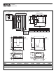
Drain Cut-Out
Fixture
Blocks
Finished Unit Depth
Minimum Alcove Depth
Unit Rough-In Depth
Drain Center
Drain
Center
Alcove Lenght / Unit Lenght
Drain Cut-Out
Drain
Cut-Out
B
C
D
5"
F
E
A
NOTE: Left End Drain
Installation Illustrated
MODEL
141000
141004
A
60"
60"
B
33"
34-1/2"
C
31-1/2"
33"
D
15-1/2"
15-1/2"
E
9-1/2"
8"
34 1/2"
33"
3 3/16"
1 1/2"
53 5/8"3 3/16"
60"
17 1/2"
52"
8"
13"
16"
73 1/2"
2" ABFLR
15 1/2"
56"
1 1/2"
60"60"
13 1/4"
73 1/2"
1 1/2"
56"16"
Ø 2-1/2" Overflow
33"
31 1/2"
15 1/2"
50 1/2"9 1/2"
55 1/2"
1 1/2"
16"
Ø 2" drain
60"
1 3/4" ABFLR
13 3/4"
141000
CM-60 R
CM-60 L (Shown)
141004
GB-60 R
GB-60 L (Shown)
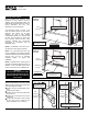
Header for Optional Cap Illustrated
(required only for units installed with cap)
Face of
Header
Ceiling
Dbl. 2 x 4 Stud
(see plan view)
2 x 4
2 x 4
Bottom
Plate
HEADER DETAIL
21" W x 16" H
Pump Access
Mandatory
on All Whirlpool
Equiped Units
Figure 1 - Unit Data, Dimensional and Alcove Framing Guidelines (Tolerance: +0/ -3 /8 inch)
Unit Sump Bottom Dry Unit Avg. Oper. Max. Sump Base Floor
Model Surface Dim. (W x L) Weight (1) Volume Capacity Area Loading
141000 Gelcoat 16 x 42 in. 116 lb. N/A 36 gal. N/A N/A
141004 Gelcoat 16 x 42 in. 144 lb. 30 gal. 36 gal. N/A N/A
1. Dry unit weight includes whirlpool system.