
User's Manual


6
1. The Microphone
This microphone has been recreated to meet the demand for the
“tube sound“ with the design approach of today using modern
componentry around the “heart“ of the microphone – the origi-
nal, specially selected 6072 tube. It should be stressed at this
point, that vacuum tubes with their heater filaments are much
more delicate than solid-state components. Consequently, the
user has to take great care in handling the microphone. Drops
from even moderate heights may cause the filament to break
and would result in immediate failure of the microphone.
It would be advisable for the users to keep a spare tube – spe-
cially selected by an AKG Service Departement – always rea-
dy for replacement.
How to replace the vacuum tube?
IMPORTANT: Prior to disassembling the microphone, make
sure to disconnect the microphone from the N 12 VR power
supply.
Turn the three grub screws at the lower end of the microphone
into the body in clockwise direction until the outer housing can
be pulled off in downwards direction.
The vacuum tube can now be removed by depressing the lower
(rubber) shockmount to free the tube with a foreward motion.
Hold the tube base in one hand and use a small, flat screwdri-
ver to carefully prize the tube from the base. Insertion of a new
tube should be done in reverse order of the description above.
If you need help to perform the above operation, please contact
your nearest AKG service center.
How to change the sensitivity of the microphone?
IMPORTANT: Prior to disassembling the microphone, make
sure to disconnect the microphone from the N 12 VR power
supply.
The circuit design incorporates the facility to increase the nomi-
nal sensitivity of the microphone by 10 dB. This basic change
to the microphone’s data may be made by the user in the follow -
ing
manner:
1. Open the microphone according to the description in the last
paragraph.
2. On the top left corner of the transformer board are three
small p. c. board switches placed next to each other. Chan-
ge all three switches to the opposite position with a small
object, like ball-pen or similar.
3. Close the microphone in reverse order of the opening pro-
cedure.
How to mount the microphone?
A special shock mount/stand adapter H 15/T is provided and
should always be used to mount the microphone on floor stands
or booms. The clamp of the shockmount should be guided from
the lower end of the microphone upwards until it is placed near
the gravitational centre (slightly below the engraving). The
shockmount can now be placed with the microphone on stands
or booms with thread sizes of 3/8 or 5/8 inch. It may also be
swivelled against the stand axis to suit the recording angle.
Powering of the microphone:
The required power unit N 12 VR is included in the delivery. It
is clearly marked and quite obvious by connector type and
size, how to connect the microphone to the power unit with the
10 m (30 ft.) multicore cable MK-Tube. The audio frequency
may be taken from the power unit transformer balanced by a
conventional audio cable with standard XLR-type connector.
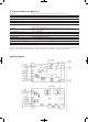
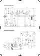
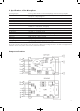
Please see the circuit diagram for wiring details.
2. The Power Unit N 12 VR
SAFETY INSTRUCTIONS: Use the equipment in dry rooms
only. Do not expose the equipment to rain or splash water.
Never place objects containing liquids (e.g., vases) on or near
the equipment.
WARNING: Parts inside the equipment may carry danger-
ous voltages. Make sure to disconnect the equipment from
power before opening the equipment!
This device not only supplies the microphone with the filament
and plate voltage for the vacuum tube, but facilitates also the
control of polar pattern and bass cut remotely from the micro-
phone. Prior to connecting the N 12 VR to AC power, check the
AC voltage of the power line you are going to connect the
N 12 VR to.
For any external wiring, do not use any cables other than
those recommended in this manual.
Check that the N 12 VR AC voitage selector to the right of the
power switch on the front panel is set to the same AC voltage.
If it is not, use a flat-blade screwdriver to set the AC voltage
selector to the correct voltage.
Warning: Connecting the N 12 VR to the wrong AC voltage
may destroy the unit and cause fire and/or electric shock.
Replacing Fuses
WARNING: Make sure to replace the built-in fuse with a
stand ard fuse of the same type only. Using any other type of
fuse may cause excessive heating and/or a risk of fire.
The fuse protecting the primary circuit is located in the
marked fuse compartment below the power connector.
Use a flat-blade screwdriver to open the fuse compartment lid.
Replace the fuse with a new fuse of the same type (T 100 mA)
and close the fuse compartment lid.
The 50-mA, fast-blow fuse protecting the anode circuit is
located on the circuit board inside the unit.
Disconnect the unit from AC power by unplugging
the power cable.
Remove the four screws fastening the top panel.
Remove the top panel.
Replace the fuse with a new 50-mA, fast-blow fuse.
Replace the top panel and fastening screws.
Power Connector
Prior to connecting the equipment to power, check that the
pow er outlet is a standard type with a protective ground con-
nection. Disconnecting the protective ground lead or using
non-standard power plugs or non-standard power outlets is il-
legal.
Especially on tour, you may need to connect the unit to a power
outlet that does not match the power connector on the supplied
power cable.
Purchase a matching power cable locaily that complies with IEC
and local safety standards and has a power connector with a
chassis ground pin. While in the same area, use this “local”
power cable only.
Should it be required to increase the connection between the
microphone and the power unit beyound 20 metres, an adap-
tion within the power unit N-Tube becomes necessary.
According to the circuit diagram, a simple change of the fuse
link marked 250 mA from its fuse holder to the one next to it
marked > 20 m is all, which is required.