AS16x12 16 Channel Automatic Matrix Mixer OPERATING INSTRUCTIONS and trouble-shooting guide
INTRODUCTION The AS16x12 is the most advanced automatic matrix mixer available today. Combining 16 automatic input channels, 12 output channels, and a full crosspoint matrix system into 2 rack spaces, the AS16x12 is a compact solution for a wide variety of sound system applications. 15 nonvolatile preset memory positions mean complete flexibility and reconfigurability. The 16 automatic inputs utilize the patented Proportional Gain plus Autoskew mixing algorithm* for seamless automatic mixing performance.
GENERAL TECHNICAL DESCRIPTION The AS16x12 uses a straightforward analog signal path to provide excellent audio performance. This is coupled with a sophisticated microcontroller to implement the automatic mixing, matrix control, room combining, and programmable input and output functions. The Adaptive Level Proportional automatic mixing algorithm is used by the AS16x12. This algorithm uses the signal level pattern at the microphones to derive a pattern of channel gains.
INSTALLATION Because it is so highly integrated, the AS16x12 is straightforward to install. The following sections explain the installation and wiring, as well as the software setup of the AS16x12. AS16X12 AUDIO INPUTS Each of the 16 AS16x12 inputs is balanced, and provides 15V phantom power (through 2K ohm feed resistors to the “+” and “-” input connections). Phantom power is switchable on a perchannel basis.
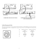
It is permissible to run LEDs from the +5VDC pins on the programmable input connector, as long as the total LED current for all LEDS on does not exceed 100mA. Similarly, 5V relay coils may also be run from the +5VDC pins on the programmable input connector, as long as the total coil current for all relays on does not exceed 100mA. Note that the diagram shows an external DC source powering the relay coil. This will be necessary if coil voltages above 5V are needed.
CONNECTING THE AS16X12 TO THE AS8 CONNECTING THE AS16X12 TO THE TH3A AND A VIDEO RECORDER LECNET EXPANSION IN/OUT When other LecNet devices are used in conjunction with the AS16x12s, the LecNet Expansion ports of these devices must also be interconnected. Refer to the diagrams above for proper interconnections. The LecNet Expansion In and Out pinouts are shown below.
FRONT PANEL DESCRIPTION CHANNEL ACTIVITY LEDS - Indicates channel activity. The LEDs light when the attenuation applied by the automatic mixing algorithm is less than or equal to 6dB. The indication of channel activity is responsive to the Input Qualification and Output Hold time parameters, which may be set in the Miscellaneous tab of the AS16x12 control panel. RESET DEFAULTS button - This button will reset the unit to factory defaults when held down while the power switch is turned on.
REAR PANEL DESCRIPTION MIC/LINE INPUTS 1-16 - Accepts balanced or unbalanced signal. Fully balanced differential input, RF filtered. GAIN SELECTION SWITCHES 1-16 - Allows input channel gain to be set. 0dB gain, for line level sources, is set when both switches of the pair are in the up position. 30dB gain, typically for high output (electret) microphones, is set when the left switch is in the up position and the right switch is in the down position.
OPERATING INSTRUCTIONS Since most of the parameters used to set up the AS16x12 are adjusted using the AS16x12 Software Control Panel, the operating instructions include instructions for the use of the software. It is recommended that you have the software running, either live or in the demo mode, as you read through this section. Power Up When the AS16x12 is powered on, it automatically loads the active setup from Preset 1.
Input Gain Tab Each input channel has two gain control points, in addition to the rear panel preamp gain switches. The input control point labeled “Input Trim” is adjusted using the Input Gain tab on the AS16x12 control panel. This control is used to adjust the sensitivity of each microphone or line level input to the desired gain. The gain adjustment range is +15dB to -63dB plus off. You may want to increase the mic preamp gain if you find that your input gain settings are routinely above +10dB.
Mute In: Used to mute one or more inputs with a switch closure. Subsequent contact closures toggle between mute and unmute. You can also assign a programmable output to reflect the programmable input state of the programmable inputs you’re using for input muting to drive LEDs for visual feedback of the mute/unmute state of the inputs. Mute Out: Used to mute one or more outputs with a switch closure. Subsequent contact closures toggle between mute and unmute.
AS16X12 CONTROL PANEL SOFTWARE The following section is a description of the File menu and each of the tabs in the AS16x12 Control Panel application. FILE MENU OPTIONS Copy Preset(s) to AS16x12 from Disk File... - Allows any preset stored to a disk file (.amd file extension) to be loaded to the corresponding AS16x12 memory preset. The Preset 1 through Preset 15 selections copy a single preset, while the All Presets selection copies all 15 presets to the AS16x12.
Update AS16x12 Firmware from Disk File - Allows newer firmware revisions to be loaded into the AS16x12. From time to time, new features or bug fixes will be added to the AS16x12’s firmware. These changes will be distributed with the LecNet installation disks and available on the Lectrosonics Web site (www.lectrosonics.com). The firmware file will have a “.s19” extension. When installing from the installation disks, the firmware files will automatically be placed in the LecNet directory (default: c:\lecnet).
to 8 separate mixers can be configured with the AS16x12. If an input is assigned to “None”, it will neither affect any other channel’s automatic gain or be affected by another channel. Short Cuts: A left mouse click on the NOM box will associate the input with NOM bus 1, while a right mouse click will set the association to “None”. On LED - Indicates that the attenuation applied to the input as a result of the automatic mixing action is less than 6dB.
MATRIX SETUP TAB The Input/Output Matrix tab sets the input to output assignments for the AS16x12. Input/Output Crosspoint -Allows the input/output crosspoint gain to be set. Each of the 12 rows of 18 crosspoint boxes represent input connections which may be set from inputs to outputs 1-12. To set a crosspoint gain, simply click on the crosspoint box at the intersection of the desired input and desired output.
OUTPUT GAIN TAB The Output Gain tab allows the output gain levels to be set. Gain, Outputs 1 - 12 - Allows the output gain to be set between +10dB and -68dB or “Off”. The background color of the output gain box will change from white to red if the output is muted by actuation of the Mute Output function of a programmable input. The output gain scroll bar will also be disabled while the output is muted.
Push Input Button - Allows a contact closure to be simulated for the current programmable input. This is useful when testing to see that the changes you’ve made to each programmable input indeed have the intended effect. Each click on the “Push Input...” button has the same effect as a momentary contact closure on the current programmable input. Note that the caption on the Push Input button always reflects the current programmable input.
Increase In 1dB / Decrease In 1dB Allows one or more input gains to be controlled by a contact closure on a programmable input pin. Increase and Decrease input gain control goes from a maximum of 0dB gain to a minimum of 30dB attenuation, plus “Off”. The gain change resolution is 1dB. In the case of Increase In 1dB, each contact closure will increment the input(s) gain by 1dB until 0dB is reached.
Increase Out 1dB / Decrease Out 1dB - Allows one or more output gains to be controlled by a contact closure on a programmable input pin. Increase and Decrease output gain control goes from a maximum of 0dB gain to a minimum of 30dB attenuation, plus “Off”. The gain change resolution is 1dB. In the case of Increase Out 1dB, each contact closure will increment the output(s) gains by 1dB until 0dB is reached.
Toggle Crosspoint Gain - Allows for a temporary matrix connection to be made between one input and any combination of outputs, at any one of the available crosspoint matrix gains. The first momentary contact closure on the programmable input pin will make the specified input-to-output(s) connection, and the next momentary contact closure will remove the connection. No matrix crosspoints other than the ones specified are changed.
Mute in / Mute out - Allows one or more inputs (Mute In) or outputs (Mute Out) to be temporarily muted. The first momentary contact closure on the programmable input pin will mute the specified input(s) or output(s), and the next momentary contact closure will unmute them. The screen to the right shows that programmable input 1 is set to mute inputs 1, 2, 3, and 4. Not Used - Deactivates a programmable input such that there will be no action associated with it. PROG.
Programmable Output Status “LED” - Shows the current state of a programmable output. If the programmable output function is set to “Channel Activity”, the LED will light any time any of the associated input channel(s) are active.
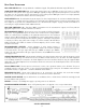
Function Analog In Control Increase In 1dB: Decrease In 1dB: Analog Out Control Increase Out 1dB: Decrease Out 1dB: Memory Preset: Toggle Crosspoint Gain: Mute In: Mute Out: State when LED On Attenuation < 15dB Contact closure on prog input Contact closure on prog input Attenuation < 15dB Contact closure on prog input Contact closure on prog input Associated memory is active Input-to-output(s) connection made Associated input(s) not muted Associated output(s) not muted State when LED Off Attenuation > 15d
A room boundary is simply a movable partition between two rooms which is removed when the two rooms are combined. When the AS16x12 “connects” two or more rooms, it automatically associates all the mic/line inputs which are physically located in the combined rooms with one NOM bus. This essentially creates one automatic mixing system out of all of the mics in the combined rooms. When the rooms are subsequently uncombined, the NOM bus associations will be separated automatically as well.
MISC SETTINGS TAB The Misc Settings tab allows various AS16x12 parameters to be set. Rear Panel Input Controls -Allows the rear panel input gain (i.e. any gain control using programmable inputs) control adjustment range to be set to safe levels for user adjustment. The maximum adjustment range of the rear panel input control goes from 0dB to 30dB (in 1dB steps) plus Off. The Min Gain scroll bar allows the gain adjustment range below 0dB to be limited as needed for the application.
Expansion In/Out Port Setup - Allows any combination of the 16 input channels to be routed to the mix minus audio bus of the rear panel Expansion Input port. This signal is typically used by the TH3A (for teleconferencing and video conferencing applications) or the TA1 (for video conferencing applications) as the near end signal to be sent to the far end. In addition, the Expansion In NOM bus may be set to participate in any of the 8 internal NOM busses.
TROUBLESHOOTING Here are a few tips for diagnosing problems: 1) If you get no sound (and the AS16x12 power is on), first check the Input Gain tab. If the number in the Gain box is too low, you might want to turn it up a bit. If the Gain box has a red background, it means the input has been muted. This is only possible from the programmable inputs.
SERIAL CABLE WIRING DIAGRAMS The serial port on the AS16x12 is a minimal RS-232 implementation. The figure shows the wiring diagram to accommodate interconnection with either a 9 or a 25 pin serial port on a PC or other serial device. AMX P ROGRAMMING NOTES If you are using an AMX system to control your LecNet equipment, you’ll want to purchase the Lectrosonics PT3 Protocol Translator. The PT3 connects between the AMX bus and any LecNet equipment.
SERIAL PORT COMMANDS AVAILABLE All LecNet devices use a modification of the typical one-to-one connection between two RS-232 compatible devices. LecNet devices have both an RS-232 transmitter and receiver section. The transmitter section is “tri-stated”, or placed in a high impedance mode, until the particular device is addressed.
GENERAL DEVICE COMMANDS Get Name String - Gets the AS16x12’s “name” string. The first data byte is the length of the name string, and the rest of the data bytes are the device name. Host sends command - 1 (1 hex) Host receives 7 bytes: Byte 1 is the length of the name string (6 for the AS16x12), bytes 2 - 7 are the ASCII values for “AM1612” (65, 77, 49, 54, 49, 50). Set Device Address - Sets the AS16x12’s device address and stores the new address in nonvolatile memory.
Set Input Gain - Sets the input gain of 1 or more input channels. Host sends command - 30 (1E hex) Host sends 5 bytes: Bytes 1-4: 16 bit mask, where each bit position represents one of the 16 inputs. For example, the lowest bit of the mask represents input 1, the next lowest bit input 2, and so on.
OUTPUT RELATED COMMANDS Get Output Gain - Gets the output gain associated with any one output or all 12 outputs. This gain value is the same one you can manipulate from the Output Gain tab on the AS16x12 control panel. Host sends command - 61 (3D hex) Host sends 1 byte: output number to return, 0 - 11 (0-B hex) returns the single gain value from outputs 1 -11, while 12 (C hex) returns 12 bytes representing the output gain of all outputs, starting with output 1.
Set Multiple Input Crosspoint Gains to One Output - Sets the crosspoint gain from any combination of the 16 inputs to any one output to a specified gain. Host sends command - 88 (58 hex) Host sends 6 bytes: Bytes 1-4: A 16 bit mask, where each bit position represents one of the 16 inputs. For example, the lowest bit of the mask represents input 1, the next lowest bit input 2, and so on.
SPECIFICATIONS Mic/Line Input Type: Impedance: Input Gain Settings: Input Gain Range: EIN, 20-20KHz: Maximum Input Level: Tone Controls: Line Outputs Impedance: Output Gain Range: Max output level: Electronically balanced and RF filtered Greater than 2.
SERVICE AND REPAIR If your system malfunctions, you should attempt to correct or isolate the trouble before concluding that the equipment needs repair. Make sure you have followed the setup procedure and operating instructions. Check out the interconnecting cords and then go through the TROUBLE SHOOTING section in the manual. We strongly recommend that you do not try to repair the equipment yourself and do not have the local repair shop attempt anything other than the simplest repair.
Limited Warranty Valid only in the United States. AKG Acoustics warrants AKG products against defects in material or workmanship for a period of one year from the date of original purchase for use, and agrees to repair or, at our option, replace any defective unit without charge for either parts or labor.