
User Guide

A room boundary is simply a movable partition between two rooms which is removed when the two rooms are combined.
When the AS16x12 “connects” two or more rooms, it automatically associates all the mic/line inputs which are physically
located in the combined rooms with one NOM bus. This essentially creates one automatic mixing system out of all of the
mics in the combined rooms. When the rooms are subsequently uncombined, the NOM bus associations will be separated
automatically as well. The AS16x12 also intelligently manages the volume controls in each room, and combines their
functions as rooms are combined together.
It is important to note that the room combining parameters which you set in the Room Combining tab are stored in the
AS16x12 as global presets. This means that the room combining scenario you set up will be the same regardless of the
particular AS16x12 preset memory which is active. The only exception to this is the Active/Not Active status of room
combining. This status value is unique to each preset memory. The result is that preset memory 1 might be set for room
combining active, and this would be your room combining setup. Preset memory 2 could be set for room combining not
active, in which case you can use the AS16x12 in any way that meets your needs.
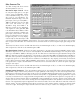
The following section describes in detail each of the programmable room combining functions.
Room Combining Active / Not Active - Sets the status of the entire room combining system. In the Active mode, the
AS16x12 is set to implement the room combining function. Programmable inputs are automatically assigned for room
boundary connecting and volume control. Programmable outputs are assigned to reflect the status of the room boundaries
(i.e. connected or not connected). The programmable input and output assignments are reflected in the Prog Inputs and
Prog. Outputs tabs, but they can not be changed there.
Number of Rooms - Allows the selection of the total number of rooms in the uncombined state. One of the three selections
must be made in order for the Apply button to function. Both room boundary and input-to-output selections will be enabled
based on the number of rooms selected.
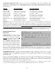
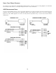
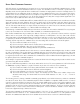
Room Boundaries - Allows the selection of the combinable boundaries based on the physical
layout of the rooms. Consider room layouts A and B as shown: Layout A requires you to select
the 1<->2 and 2<->3 Room Boundary options, since there are only two combinable
boundaries. Layout B has one more boundary because of the different physical layout. In this
case, you would select the 1<->2, 2<->3, and 1<->3 Room Boundary options, as the layout
introduces the extra boundary between room 1 and room 3.
Inputs-to-Outputs - Allows the assignment of inputs to the output connected with each
uncombined room. The inputs are assigned to outputs based on the physical location of the
inputs drop in the uncombined rooms. For example, all input drops physically located in
Room 1 should be assigned to Output 1. Similarly, Room 2 input drops should be assigned to
Output 2, etc.
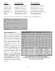
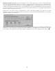
Volume Switch Programmable Input Assignment - Shows the assignment of
programmable input pins made by the AS16x12 control panel for room volume control. For
each room, you’ll see a Volume Up and Volume Down line. This line includes the programmable input number assignment,
as well as the actual pin number on the 25 pin Programmable Inputs D-sub connector on the rear panel.
Simple momentary contact switches from the specified programmable input to ground will allow user adjustment of the
room volume. When rooms are combined, all volume control switches in the combined room affect the volume of all rooms
in the combined room.
Boundary Switch Programmable Input Assignment - Shows the assignment of programmable input pins made by the
AS16x12 control panel for room boundary connection switches. For each boundary you’ve selected, you’ll see a line. This
line includes the programmable input number assignment, as well as the actual pin number on the 25 pin Programmable
Inputs D-sub connector on the rear panel. Simple momentary contact switches from the specified programmable input to
ground will allow user connection and disconnection of rooms. Note that when the control panel makes the boundary
switch assignments, it automatically makes programmable output assignments for each of the programmable inputs which
are boundary switches. These may be used to drive LED indicators located near the combine switches to give the user
feedback about the state of a particular room boundary.
24
Layout A
Layout B
12 3
1
12