
User Guide


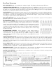


It is permissible to run LEDs from the +5VDC pins on the programmable input connector, as long as the total LED current
for all LEDS on does not exceed 100mA. Similarly, 5V relay coils may also be run from the +5VDC pins on the
programmable input connector, as long as the total coil current for all relays on does not exceed 100mA. Note that the
diagram shows an external DC source powering the relay coil. This will be necessary if coil voltages above 5V are needed.
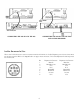
AUDIO EXPANSION IN/OUT
When multiple AS16x12s are used in an application, their Audio Expansion ports must be interconnected using the Audio
Expansion In/Out connectors on the rear panel of the AS16x12. These two 30 pin headers are just to the right of the LecNet
(RS232) jack on the rear panel. A 3" 30 conductor ribbon cable is supplied with each AS16x12 for this purpose. When
installing the AS16x12s in a rack, the Master AS16x12 should be mounted in the top of the rack, with Slave AS16x12s
mounted below the Master AS16x12. The ribbon connector then connects the Audio Expansion In connector of the Master
AS16x12 to the Audio Expansion Out connector of the first Slave AS16x12. If there are more than one Slave AS16x12s,
the Audio Expansion In connector of the first Slave AS16x12 is connected to the Audio Expansion Out connector of the
second Slave AS16x12, and so on for as many Slave AS16x12s as exist in the system.
5
AS16x12 Rear Panel
TH3A Rear Panel
CONNECTING MULTIPLE AS16X12S TOGETHER CONNECTING THE AS16X12 TO THE TH3A
To additional AM16x12s