AVR 135 Audio/Video Receiver OWNER’S MANUAL Power for the Digital Revolution®
Table of Contents 3 4 4 5 7 9 12 12 12 13 14 14 15 15 15 15 16 16 19 19 20 20 21 23 23 25 25 25 26 26 27 27 27 27 27 27 28 28 28 29 29 29 30 31 31 31 31 31 32 33 33 33 33 33 33 33 34 35 35 35 35 35 36 36 36 Introduction Safety Information Unpacking Front Panel Controls Rear Panel Connections Remote Control Functions Installation and Connections Audio Equipment Connections Video Equipment Connections SCART A/V Connections AC Power Connections Speaker Selection and Placement System Configuration First Turn O
Introduction Thank you for choosing Harman Kardon! With the purchase of a Harman Kardon AVR 135 you are about to begin many years of listening enjoyment. The AVR 135 has been custom designed to provide all the excitement and detail of movie sound tracks and every nuance of musical selections. With onboard Dolby* Digital and DTS† decoding, the AVR 135 delivers six discrete channels of audio that take advantage of the digital sound tracks from the latest DVD and LD releases and Digital Television broadcasts.
Safety Information Important Safety Information Verify Line Voltage Before Use Your AVR 135 has been designed for use with 220-240-Volt AC current. Connection to a line voltage other than that for which it is intended can create a safety and fire hazard and may damage the unit. If you have any questions about the voltage requirements for your specific model, or about the line voltage in your area, contact your dealer before plugging the unit into a wall outlet.
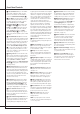
Front Panel Controls 1 Main Power Switch 2 System Power Control 3 Power Indicator 4 Headphone Jack 5 Surround Mode Group Selector 6 Speaker Select Button 7 Selector Buttons 8 Tone Mode 9 Surround Mode Selector ) Tuning ! Tuner Band Selector @ Set Button # Preset Stations Selector $ Speaker/Channel Input Indicator % Input Source Selector ^ RDS Select Button & Delay * Digital Optical 3 Input ( Surround Mode Indicators Ó Digital Coax 3 Input Ô Video 3 input jacks Bass Control Ò Balance Control Ú Treble Co
Front Panel Controls 7 Selector Buttons: When you are establishing the AVR’s configuration settings, use these buttons to select from the choices available, as shown in the Main Information Display ˜. 8 Tone Mode: Pressing this button enables or disables the Balance, Bass and Treble tone controls. When the button is pressed so that the words TONE I N appear in the Main Information Display ˜, the settings of the Bass and Treble Ú controls and of the Balance control Ò will affect the output signals.
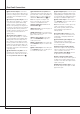
Rear Panel Connections a ∞£ § ¢ b · d ° ¤ ¶ e ° · d b ‡ fl ¤ ª fi 135 • ™ ¡ ⁄ f ‹ › ‹ ‚c g h i Tape Inputs Tape Outputs Video 1 Audio Inputs AM Antenna Video 1 Audio Outputs DVD Audio Inputs FM Antenna CD Inputs Digital Audio Outputs Coaxial Digital Inputs Subwoofer Output Tape Inputs: Connect these jacks to the PLAY/OUT jacks of an audio recorder.
Rear Panel Connections Video Monitor Outputs: Connect these jacks to the composite and/or S-Video input of a TV monitor or video projector to view the output of any video source selected by the receiver’s video switcher. Unswitched AC Accessory Outlet: This outlet may be used to power any AC device. The power will remain on at this outlet regardless of whether the AVR is on or off (in Standby), provided that the Main Power switch 1 is on.
Remote Control Functions 0 1 2 3 4 5 6 7 8 9 A B C D E F G H I J K L M N O P Q ! " # $ % & ' ( ) * + Power Off Button IR Transmitter Window Program/SPL Indicator Power On Button Input Selectors AVR Selector AM/FM Tuner Select 6-Channel/8-Channel Direct Input Test Button Sleep Button Surround Mode Selector Night Mode Channel Select Button ⁄ / ¤ Buttons ‹ Button Set Button Digital Select Numeric Keys Tuner Mode Direct Button Tuning Up/Down OSD Button Dolby Mode Select Button DTS Digital Mode Selector L
Remote Control Functions IMPORTANT NOTE: The AVR’s remote may be programmed to control up to seven devices, including the AVR. Before using the remote, it is important to remember to press the Input Selector button 4 that corresponds to the unit you wish to operate. In addition, the AVR’s remote is shipped from the factory to operate the AVR and most Harman Kardon CD or DVD players and cassette decks.
Remote Control Functions L OSD Button: Press this button to activate the On Screen Display (OSD) system used to set up or adjust the AVR’s parameters. M Dolby Mode Selector: This button is used to select one of the available Dolby Surround processing modes. Each press of this button will select one of the Dolby Pro Logic II modes, Dolby 3 Stereo or Dolby Digital.
Installation and Connections After unpacking the unit, and placing it on a solid surface capable of supporting its weight, you will need to make the connections to your audio and video equipment. Audio Equipment Connections We recommend that you use high-quality interconnect cables when making connections to source equipment and recorders to preserve the integrity of the signals.
Installation and Connections SCART A/V Connections For the connections described above your video device needs RCA (cinch) connectors or/and SVideo connectors for all Audio and Video signals: Any normal video device (Not SVHS or High 8) for only playback needs 3 RCA jacks, VCRs for record and playback even 6 RCA jacks. Any S-Video device (SVHS, High 8) needs 2 RCA (Audio) and 1 S-Video jack (Video), if it´s a playback unit, or 4 RCA (Audio In/Out) and 2 S-Video (Video In/Out) jacks, if it´s a recording VCR.
Installation and Connections AC Power Connections This unit is equipped with two accessory AC outlets. They may be used to power accessory devices, but they should not be used with highcurrent draw equipment such as power amplifiers. The total power draw to the Unswitched Outlet must not exceed 100 watts, that to the Switched Outlet 50 watts. The Switched outlet will receive power only when the unit is on completely.
System Configuration Once the speakers have been placed in the room and connected, the remaining steps are to program the system configuration memories. With the AVR two kind of memories are used, those associated individually with the input selected, e.g. surround modes, and others working globally for all inputs selected like speaker output levels, crossover frequencies or delay times used by the surround sound processor.
System Configuration To make this process as quick and as easy as possible, we suggest that you use the full-OSD system with the on-screen menus, and step through each input. Input Setup The first step in configuring the AVR is to select an input, i.e. to associate an analog or digital input with each input source in use, e.g. CD or DVD.
System Configuration listening to music through a CD player as opposed to a movie from a DVD player, VCR or cable/satellite set top. If you wish to customize the speaker size individually to each input, make certain that the cursor is on the BASS MGR line and press the ‹/ › Buttons E& so that INDEPENDENT appears in highlighted video. When this setting is entered all speaker size settings will be shown with their factory default size in the menu and all other inputs will turn to INDEPENDENT too.
System Configuration The choices available for the subwoofer position will depend on the settings for the other speakers, particularly the front left/right positions. If the front left/right speakers are set to SMALL, the subwoofer will automatically be set to SUB, which is the “on” position. one of the settings, please proceed by pressing the Button D so that the cursor moves back up to the top of the list of setting options.
System Configuration As an example, in the Figure below, all speakers are set for “large,” and a subwoofer is set. SMALL or LARGE the AVR will be configured for 6.1/7.1-channel operation, and additional modes such as Dolby Digital EX and DTS-ES will appear, as they are only available when six main speakers are present. In addition, the modes DTS ES (Discrete) and DTS+NEO:6 (DTS ES Matrix) available in the AVR will not appear unless a digital source is playing the correct bitstream.
Operation On the DTS menu, the selection choices made with the ‹ / › Buttons E& on the remote are determined by a combination of the type of DTS program material in use and whether the 5.1 or 6.1/7.1 speaker output configuration is in use. When the 5.1 configuration is in use the AVR will automatically select the 5.1 version of DTS processing when a DTS data stream is received. When the 6.1/7.
Operation round mode is selected (except Dolby-3-Stereo). In addition they are selectable with these modes only, with all other modes the delay times are fixed. Note that the Delay settings are "Global" for all inputs, using those Dolby modes, and need not to be repeated with any input. To start with the delay settings at first select any input associated with such a Dolby mode. Next, continue within the MASTER M E N U (Figure 1).
Operation IMPORTANT NOTE: Because this test noise will have a much lower level than normal music, the volume must be lowered after the adjustment for all channels is made, but BEFORE you return to the main menu and the test tone turns off. 5. Remember to verify that the speakers have been properly connected. As the test noise circulates, listen to make certain that the sound comes from the speaker position shown in the Main Information Display ˜.
Operation Surround Mode Chart MODE FEATURES DELAY TIME RANGE DOLBY DIGITAL Available only with digital input sources encoded with Dolby Digital data. It provides up to five separate main audio channels and a special dedicated Low Frequency Effects channel. Center: 0 - 30ft / 9m Initial Setting: 12ft / 3.6m Surround: 0 - 30ft / 9m Initial Setting: 10ft / 3m DOLBY DIGITAL EX Available when the receiver is configured for 6.1/7.1 channel operation, Dolby Digital EX is the latest version of Dolby Digital.
Operation Surround Mode Chart MODE FEATURES DELAY TIME RANGE DTS Neo:6 Cinema DTS Neo:6 Music These two modes are available when any analog source is playing to create a six-channel surround presentation from conventional Matrix-encoded and traditional Stereo sources. Select the Cinema version of Neo:6 when a program with any type of analog Matrix surround encoding is present. Select the Music version of Neo:6 for optimal processing when a nonencoded, two-channel stereo program is being played.
Operation Basic Operation Once you have completed the setup and configuration of the AVR, it is simple to operate and enjoy. The following instructions should be followed for you to maximize your enjoyment of your new receiver: Turning the AVR On or Off • When using the AVR for the first time, you must press the Main Power Switch 1 on the front panel to turn the unit on. This places the unit in a Standby mode, as indicated by the amber color of the Power Indicator 3.
Operation Controls and Use of Headphones Surround Mode Selection • Adjust the volume to a comfortable level using the front panel Volume Control ı or remote Volume Up/Down ) buttons. One of the most important features of the AVR 135 is its ability to reproduce a full multichannel surround sound field from digital sources, analog matrix surround encoded programs and standard stereo or even mono programs. • To temporarily silence all speaker outputs press the Mute button (.
Operation Digital Audio Playback Digital audio is a major advancement over older analog surround processing systems such as Dolby Pro Logic. It delivers five or six discrete channels: left front, center, right front, left surround and right surround and with DTS ES (see below) even surround back (with identical signals for left and right). Each channel reproduces full frequency range (20Hz to 20kHz) and offers dramatically improved dynamic range and significant improvements to signal-to-noise ratios.
Operation Surround Mode Types For Dolby Digital and DTS sources, a three digit indication will appear, showing the number of channels present in the data. An example of this type of display is 3/2/.1. The first number indicates how many discrete front channel signals are present. • A 3 tells you that separate front left, center and front right signals are available. This will be displayed for Dolby Digital 5.1 and DTS 5.1 programs.
Operation Important Note: When a digital surround source (Dolby Digital, DTS) is played, the letters SBL/SBR for the Surround Back channels will appear only when a DTS ES DISCRETE 6.1 source is played. Then this surround mode will be indicated in the front display and on-screen display.
Operation Repeat the procedure as needed until all channels requiring adjustment have been set. When all adjustments have been made and no further adjustments are made for five seconds, the AVR will return to normal operation. NOTE: The output levels may be separately trimmed for each digital and analog surround mode. If you wish to have different trim levels for a specific mode, select that mode and then follow the instructions in the steps shown above.
Advanced Features The AVR 135 is equipped with a number of advanced features that add extra flexibility to the unit’s operation. While it is not necessary to use these features to operate the unit, they provide additional options that you may wish to use. Front-Panel-Display Fade In normal operation, the front-panel displays and indicators remain on at full brightness, although you may also dim them or turn them off as shown on page 31.
Advanced Features Press the ⁄ Button D, until the on-screen ➞ cursor is next to the ADVANCED line. Press the Set Button F to enter the ADVANCED SELECT menu. At the ADVANCED SELECT menu make certain that the on-screen ➞ cursor is next to the SEMI OSD line by pressing the ⁄/¤ buttons D as needed. Next, press the › button & so that the word OFF is shown in the video display. Note that this setting is temporary and will remain active only until it is changed or until the AVR is turned off.
Tuner Operation Basic Tuner Operation The AVR 135’s tuner is capable of tuning AM, FM and FM Stereo broadcast stations and receiving RDS data. Stations may be tuned manually, or they may be stored as favorite station presets and recalled from a 30 position memory. Station Selection 1. Press the AM/FM Tuner Select button 6 on the remote to select the tuner as an input.
Tuner Operation Some RDS stations may not include some of these additional features. If the data required for the selected mode is not being transmitted, the Main Information Display ˜ will show a N O TYPE, N O TEXT or N O TIME message after the individual time out. In any FM mode the RDS function requires a strong enough signal for proper operation.
Programming the Remote The AVR 135 is equipped with a powerful remote control that will control not only the receiver’s functions, but also most popular brands of audio and video equipment, including CD players, TV sets, cable boxes, VCRs, satellite receivers and other home-theater equipment. Once the AVR’s remote is programmed with the codes for the products you own, it is possible to eliminate most other remotes and replace them with the convenience of a single universal remote control.
Programming the Remote For future reference enter the Setup Codes for the equipment in your system here: DVD ____________ CD ________________ VID1/VCR ________ VID2/TV __________ VID3/CBL/SAT ______________________ VID4 ______________________________ TAPE ______________________________ Macro Programming Macros enable you to easily repeat frequently used combinations of commands with the press of a single button on the AVR’s remote control.
Programming the Remote 2. Press the Volume Up button ) and note that.the Program/SPL Indicator 2 will stop flashing and stay amber. 3. Press either the AVR Selector 5 or the Input Selector 4, depending on which system’s volume control you wish to have attached for the punch-through mode. The Program/SPL Indicator 2 will blink green three times and then go out to confirm the data entry.
Function List 38 FUNCTION LIST No. Button Name AVR Function DVD CD/CDR 1 2 3 4 5 6 7 8 9 10 11 12 13 14 15 16 17 18 19 20 21 22 23 24 25 26 27 28 29 30 31 32 33 34 35 36 37 38 39 40 41 42 43 44 45 46 47 48 49 50 51 52 53 54 55 56 57 58 59 60 61 62 63 64 65 66 67 Power On Power Off Mute AVR DVD CD Tape VID 1 VID 2 VID 3 DIM AM/FM 6/8 Ch.
Function List No. Button Name Tape VCR (VID 1) TV (VID 2) CBL (VID 3) SAT(VID 3) 1 2 3 4 5 6 7 8 9 10 12 13 14 16 17 18 19 20 21 22 23 24 25 26 27 28 29 30 31 32 33 34 35 36 37 38 39 40 41 42 43 44 45 46 47 48 49 50 51 52 53 54 55 56 57 58 59 60 61 62 63 64 65 66 67 68 69 Power On Power Off Mute AVR DVD CD Tape VID 1 VID 2 VID 3 DIM AM/FM 6/8 Ch.
Troubleshooting Guide SYMPTOM CAUSE SOLUTION Unit does not function when Main Power Switch 1 is pushed • No AC Power • Make certain AC power cord is plugged into a live outlet • Check to see if outlet is switch controlled Display lights, but no sound or picture • Intermittent input connections • Make certain that all input and speaker connections are secure • Press Mute button ( • Turn up volume control • Mute is on • Volume control is down Units turns on, but Front-Panel Display does not light •
Technical Specifications Audio Section Stereo Mode Continuous Average Power (FTC) 50 Watts per channel, 20Hz–20kHz, @ < 0.07% THD, both channels driven into 8 ohms 6 Channel Surround Modes Power Per Individual Channel Front L&R channels: 40 Watts per channel, @ < 0.07% THD, 20Hz–20kHz into 8 ohms Center channel: 40 Watts, @ < 0.07% THD, 20Hz–20kHz into 8 ohms Surround (L & R Side, Back) channels: 40 Watts per channel, @ < 0.
250 Crossways Park Drive, Woodbury, New York 11797 www.harmankardon.com Harman Consumer Group International: 2, route de Tours, 72500 Château-du-Loir, France © 01/2005 Harman Kardon, Incorporated Part No.