
Specifications

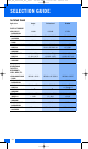


213
GLOSSARY
Antenna Cable
Cable specifically designed for RF signals.
Used for connecting a remote antenna to a
receiver. Antenna cables are typically coaxial
and symmetrical. Signal attenuation depends
on the frequency band of the signal as well as
the length and quality of the cable and is quot-
ed for a 100-m run of cable.
Antenna Splitter
Electronic network specifically designed for RF
signals. Distributes an antenna output signal
to several receivers. Powered antenna splitters
use an amplifier to compensate for cable atten-
uation while passive antenna splitters have no
amplifier.
Balanced/Unbalanced Connections
Microphones can be connected to an amplifier
with either balanced or unbalanced cables. In a
balanced cable, the signal is carried by the two
inner conductors and the shield is not part of
the signal path. Even with long cable runs, any
external interference signal (such as power line
hum) would be induced equally in both conduc-
tors and thus be canceled. Unbalanced cables
use only one center conductor as the “hot” wire,
the shield being the ground (“cold”} lead. While
this arrangement works well with cables up to
10 meters in length low-frequency, long-wave
hum interference may be picked up by longer
cables which act as a long-wave antenna.
BNC
Connector specifically designed for RF lines.
Booster
Amplifier for RF signals. Boosters are connect-
ed between a transmitter output and the anten-
na in order to increase radiated power (custom
product).
Condenser Microphone
The transducer element consists of a vibrating
diaphragm (metalized foil) only about a ten
thousandth of an inch thick and a fixed metal
electrode (back plate). The two electrodes make
up a capacitor (condenser) charged by an
externally applied DC voltage 1" polarizing volt-
age or carrying its own permanent charge. The
sound waves driving the diaphragm will vary
the capacitance of the capacitor and conse-
quently the microphone output voltage will vary
in step with the sound waves.
Condenser microphones, also called “capacitor
microphones”, need an impedance converter
(preamplifier) to match the very-high-imped-
ance condenser transducer to low-Z inputs.
Condenser microphones usually have a flat fre-
quency response, high sensitivity, and good
transient response. They require a power sup-
ply. All AKG condenser microphones are desig-
nated by the letter(s) “C” or “CK” in front of the
model number.
Connecting AKG Microphones
All handheld microphones listed in this catalog
are low-impedance 1200 to 620 incorporating a
balanced output on a 3-pin male XLR connec-
tor. Conforming to IEC 268-12, pin 1 is ground,
pin 2 high, and pin 3 low. The output is com-
patible with all mixers, tape recorders, etc.
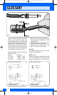
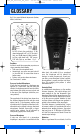
To connect an AKG microphone to an input jack,
wire the microphone cable as follows: connect
the sleeve of the jack plug (ground) to the cable
shield and the shield to pins 1 and 3 on the XLR
connector. The center (“hot”) wire connects pin
2 to the jack plug tip (see fig. 1).
If your installation uses pin 3 as “high” or
“hot”, bridge pins 1 and 2 for unbalanced con-
nections and make sure to follow the same con-
vention for all cables in order to avoid phase
reversal problems.
Very old sound systems sometimes have high-
impedance microphone inputs.
Should the signal of a low-impedance micro-
phone be too weak, insert a 1:10 step-up trans-
former at the amplifier input. Long cable runs
used with high-impedance equipment cause
high-frequency loss. The same applies if you
connect a microphone to a high-impedance
guitar amplifier input.
Connecting Condenser Microphones
Condenser microphones - except for the battery
powered C 1000 S - require an operating volt-
age that needs to be fed through the micro-
phone cable (phantom powering). This can be
done in several ways:
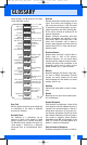
1. From a mixer with built-in phantom power
(9 to 52 V).
2. By modifying the mixer or tape recorder to
provide phantom power: find a regulated
DC voltage between 9 and 52 V in the power
7496_04_Fulline_E4_fsch 29.06.2004 13:22 Uhr Seite 213