
Specifications

2.4.1 Controls
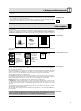
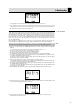
Refer to fig. 1.
1 Status LED: This bicolor LED indicates the current operating status of the transmitter:
Green: The output signal of the microphone element is fed to the transmitter, which transmits the
audio signal to the receiver.
Red: The Status LED is lit red if
- the audio signal is muted while the RF section remains active. This prevents unwanted noise from
becoming audible in the signal chain;
- approximately 60 minutes before the batteries or BP 4000 battery pack wil be dead; and
- while the transmitter recalls the carrier frequency from memory after you turned power to the trans-
mitter on. Unless you muted the audio signal, the status LED will change to green as soon as the
frequency has been recalled.
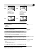
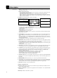
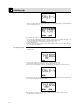
2 Display: The transmitter provides a five-line LCD display:
The display indicates all transmitter parameters:
- Carrier frequency in MHz or as a Subchannel of a Frequency Group
- Audio input level
- Battery status and remaining operating time
- Error messages
- Setup menus: Frequency, Preset, Gain
The backlighting of the display comes on every time you actuate the jog switch and will switch off after
approximately 10 seconds.
3 ON/OFF button: A long push (approx. 1.5 seconds) will switch power to the transmitter ON and acti-
vate the display (2) and status LED (1). The transmitter will be ready to operate after approx. 7 sec-
onds.
A long push (approx. 1.5 seconds) in SETUP mode or SILENT mode will switch power to the trans-
mitter OFF. In LOCK mode, the ON/OFF button is electronically locked to prevent power from being
switched off unintentionally.
The ON/OFF button is recessed for added protection from unintentional actuation.
4 MUTE switch: Sliding the MUTE switch to the MUTE position will mute the audio signal. The status
LED (1) will change to red. Since power and the RF section remain ON, no unwanted noise will
become audible from the sound system when you mute the audio signal.
To switch the audio signal back on, slide the MUTE switch to the ON position. The status LED (1) will
change to green.
The MUTE switch is active in all modes.
5 Audio input: 3-pin mini XLR connector with both mic and line level pins that automatically match the
connector pinout of the recommended AKG microphones or optional MKG/L instrument cable.
6 Jog switch: Sets the various parameters of the transmitter. The jog switch has the following functions:
Long push: toggles between LOCK and SETUP modes when the transmitter is ON. When power to
the transmitter is OFF, a long push switches the transmitter ON and places it in SILENT mode.
SETUP and SILENT modes only:
Short push: calls up a parameter for adjustment or confirms a selected value.
Turn left briefly to select a menu item or decrease a parameter value.
Turn right briefly to select a menu item or increase a parameter value.
Turn left or right and hold to scroll through available values.
7 Charging contacts: The recessed charging contacts allow you to recharge the optional AKG BP 4000
battery pack on the optional CU 4000 charger without having to remove the battery pack from the
transmitter.
8 REMOTE MUTE jack: This jack allows you to connect the optional Remote Mute switch.
9 Color code: If you use the transmitter within a multichannel system, you can remove the black paper
strip and replace it with a different-color paper strip from the supplied color coding kit to identify the
various channels. You can even write or print additional information on the paper strips.
10 Antenna: Permanently connected, flexible antenna.
11 Battery conmpartment door
12 Frequency sticker: Sticker attached to the transmitter rear panel, indicating the available carrier fre-
quency range and approval data.
13 Battery compartment accepting the two supplied 1.5 V AA size batteries or the optional BP 4000
battery pack.
14 Belt Clip for fixing the transmitter to your belt.
2 Description
16
Mode, measurement unit
Preset Name, Frequency Group,
Subchannel (Preset menu only)
Alphanumeric display of the cur-
rently active value or battery
capacity in hours
Battery capacity or audio level
bar graph
Parameter to be adjusted