TRUE RMS MULTIMETER& OSCILLOSCOPE AMM-4189 User’s Manual www.tmatlantic.
Contents Contents True RMS Multimeter....................................................................................................... 1.Introduction................................................................................................................... 2.Safety............................................................................................................................ 3.Safety Instructions......................................................................................
True RMS Multimeter Please read this manual before switching the unit on. Important safety information inside. www.cem-instruments.com www.tmatlantic.
True RMS Multimeter 1.Introduction Professional True RMS Industrial D igital Multimeter with oscilloscope functions and TFT color LCD display,providing fast A/D conver ting sampling time, high accuracy , built-in datalogging and Trend Capture feactures. It can trace any interrupted problems of the equipments and watch on without person. It is easy to find and solve the problems of the production equipments, providing Bluetooth technology and memory the datasheets.
True RMS Multimeter OVERVOLTAGE CATEGORY II Equipment of OVERVOLTAGE CATEGORY II is energy-consuming equipment to be supplied from the fixed installation. Note – Examples include household, office, and laboratory appliances. OVERVOLTAGE CATEGORY III Equipment of OVERVOLTAGE CATEGORY III is equipment in fixed installations. Note – Examples include switches in the fixed installation and some equipment for industrial use with permanent connection to the fixed installation.
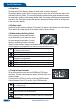
True RMS Multimeter 3-7.NEVER operate the meter unless the back cover and the battery and fuse covers are in place and fastened securely. If the equipment is used in a manner not specified by the manufacturer, the protection provided by the equipment may be impaired. 4.Feature 4-1.Understanding the Push Buttons The 12 push buttons on the front of the Meter activate features that augment the function selected using the rotary switch, navigate menus or control power to Meter circuits.
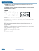
True RMS Multimeter 4-2.Understanding the Display 5 6 7 Auto Range REL 3 2 0 -5 10 9 -0 . 0 0 0 8 VDC 13:17 4 8 11 03/26/11 VAC 12 0 . 0005 13 -4 -3 -2 -1 0 1 2 3 4 14 5VAC - 23.2 dBm 1 MENU SAVE REL,% 15 SETUP 1.Soft key labels Indicates the function of the button just below the displayed label. 2.Bar graph Analog display of the input signal(See the "Bar Graph" section for more information). 3.Minus sign Indicates a negative reading. 4.
True RMS Multimeter 4-4.Page Area The page area of the display is where the main meter content is displayed. The primary display (upper half of the page area) is where the most important value of the selected function is shown. The secondary display contains the bar graph and values that may be measured in addition to the primary function value. For example, with frequency measurement selected in Vac, the frequency value will appear in the primary display with the ac voltage value in the secondary display.
True RMS Multimeter 5. Measurement and Setup 5-1.DC Voltage Measurements CAUTION: Do not measure DC voltages if a motor on the circuit is being switched ON or OFF. Large voltage surges may occur that can damage the meter. 1. Set the function switch to the green VDC position. 2.Insert the black test lead banana plug into the negative COM jack. Insert the red test lead banana plug into the positive V jack. 3.Read the voltage in the display. DT-9989 06/13/07 8:10pm DXWR UDQJH 9'& 100.
True RMS Multimeter 5-2.AC Voltage Measurements WARNING: Risk of Electrocution. The probe tips may not be long enough to contact the live parts inside some 240V outlets for appliances because the contacts are recessed deep in the outlets. As a result, the reading may show 0 volts when the outlet actually has voltage on it. Make sure the probe tips are touching the metal contacts inside the outlet before assuming that no voltage is present.
True RMS Multimeter 5-3.Making dB Measurements The Meter is capable of displaying voltage as a dB value, either relative to 1 milliwatt (dBm), a reference voltage of 1 volt (dBV) or a user-selectable reference value. 1.Set the function switch to the green VAC position. 2.press the softkey labeled Menu. Move the menu selector to the menu item labeled dBm. Press the softkey dBm 3.Insert the black test lead banana plug into the negative COM jack. Insert red test lead banana plug into the positive V jack. 4.
True RMS Multimeter 5-5.mV Voltage Measurements CAUTION: Do not measure mV voltages if a motor on the circuit is being switched ON or OFF. Large voltage surges may occur that can damage the meter. 1.Set the function switch to the green mV position. 2.Press the soft key labeled Menu. Move the menu selector to the menu item labeled mVDC(mVAC). Press the soft key mVDC(mVAC). 3.Insert the black test lead banana plug into the negative COM jack. Insert the red test lead banana plug into the positive V jack. 4.
True RMS Multimeter 5-6.Temperature Measurements 1.Set the function switch to the green TEMP(°C or °F) position. 2.press the soft key labeled Menu. Move the menu selector to the menu item labeled TEMP. Press the soft key TEMP(C or F). 3.Insert the Temperature Probe into the input jacks, making sure to observe the correct polarity. 4.Read the temperature in the display 5.To input a temperature offset value, press the softkey labeled Offset to open a message box with the present offset value.
True RMS Multimeter 5-8.Resistance Measurements WARNING: To avoid electric shock, disconnect power to the unit under test and discharge all capacitors before taking any resistance measurements. Remove the batteries and unplug the line cords. 1.Set the function switch to the green Ω CAP position. 2.Insert the black test lead banana plug into the negative COM jack. Insert the red test lead banana plug into the positive Ω Jack. 3.Read the resistance in the display. DT-9989 8:10pm 06/13/07 auto range 50.
True RMS Multimeter 5-9.Continuity Check WARNING: To avoid electric shock, disconnect power to the unit under test and discharge all capacitors before taking any resistance measurements. Remove the batteries and unplug the line cords. 1.Set the function switch to the green Ω CAP position. 2.Press the soft key labeled Menu. Move the menu selector to the menu item labeled Beeper. Press the soft key Beeper. 3.Insert the black test lead banana plug into the negative COM jack.
True RMS Multimeter 5-10.Diode Test 1.Set the function switch to the green Ω CAP position. 2.Press the soft key labeled Menu. Move the menu selector to the menu item labeled Diode. Press the soft key Diode. 3.Insert the black test lead banana plug into the negative COM jack and the red test lead banana plug into the positive V jack. 5.Forward voltage will typically indicate 0.400 to 3.200V. Reverse voltage will indicate “OL”.
True RMS Multimeter 5-11.Capacitance Measurements WARNING: To avoid electric shock, disconnect power to the unit under test and discharge all capacitors before taking any capacitance measurements. Remove the batteries and unplug the line cords. 1.Set the rotary function switch to the green Ω CAP position. 2.Press the soft key labeled Menu. Move the menu selector to the menu item labeled Cap. Press the soft key Cap. 3.Insert the black test lead banana plug into the negative COM jack.
True RMS Multimeter 5-12.DC Current Measurements CAUTION: Do not make 20A current measurements for longer than 30 seconds. Exceeding 30 seconds may cause damage to the meter and/or the test leads. 1.Insert the black test lead banana plug into the negative COM jack. 2.For current measurements up to 5000μA DC, set the function switch to the yellow μA position and insert the red test lead banana plug into the μA/mA jack. 3.
True RMS Multimeter 5-13.AC Current Measurements CAUTION: Do not make 10A current measurements for longer than 30 seconds. Exceeding 30 seconds may cause damage to the meter and/or the test leads. 1.Insert the black test lead banana plug into the negative COM jack. 2.For current measurements up to 5000μA AC, set the function switch to the yellow μA position and insert the red test lead banana plug into the μA/mA jack. 3.
True RMS Multimeter 5-14.Understanding Function Menus Each primary measurement function (rotary switch position) has a number of optional sub-functions or modes accessed by pressing the softkey labeled Menu (F1). A typical menu is shown in Figure. Menu selection is indicated by the filled-in black square(hereafter the menu selector) to the left of a menu item. Use the four front-panel cursor buttons ( ) to position the menu selector next to a menu item.
True RMS Multimeter 5-16.Measuring AC and DC Signals The Meter is capable of displaying both AC and DC signal components (voltage or current) as two separate readings or one AC+DC(RMS) value combined. As shown in Figure , the Meter displays ac and dc combinations two ways: DC displayed over AC (DC,AC), and AC combined with dc (AC+DC). Select one of these three displays using the Function and Mode menu. With the rotary switch set to V, mV, A, mA,or uA, press the soft key labeled Menu.
True RMS Multimeter To save the MIN MAX screen data, the MIN MAX session must be ended by pressing the softkey labeled Stop. Next, press the softkey labeled Save.A dialog box openswhere the default saved name can be selected or anothername assigned. the softkey labeled Save to store. Pressing the softkey labeled Restart while MIN MAX is running stops the MIN MAX session, discards all MIN MAXdata, and immediately starts a new MIN MAX recording session. 5-18.
True RMS Multimeter 5-22.Storing Individual Measurement Data For all measurement functions, a snapshot of the screen data is saved by pressing the softkey labeled Save. Edit name, then pressing the softkey labeled Save stored date. 5-23.Viewing Memory Data Viewing data stored in the Meter’s memory is performed through the save menu. Press the softkey labeled Save. Position the menu selector next to the menu item labeled View measure and press the softkey labeled View.
True RMS Multimeter 5-25.Recording Measurement Data The Meter’s record feature collects measurement information over a user-specified duration. This collection of information is called a recording session. A recording session is made up of one or more measurement records Each record contains measurement summary information covering the duration of the record. Press the softkey labeled Save.
True RMS Multimeter 5-27.Changing Meter Setup Options The Meter has a number of preset features such as date and time formats and battery save mode timeouts, and the displayed language. These variables are referred to as Meter setup options. Many setup options affect general Meter operations and are active in all functions. Others are limited toone function or group of functions. Access to the setup options is always available through the softkey labeled Setup.
True RMS Multimeter 5-32.Using Communications You can use the Wireless communication link and transfer the contents of a meter’s memory to a PC. Press the softkey labeled Setup to access the setup menu. Using the cursor buttons, move the menu selector next to the menu item labeled communicate and press the softkey labeled PC. press the softkey labeled open will start communications function; or press the softkey labeled close will close communications function.. 5-33.
True RMS Multimeter 5-37.Replacing the Fuses Referring to Figure , examine or replace the Meter's fuses as follows: 1.Turn the Meter off and remove the test leads from the terminals. 2.Remove the battery door assembly by using a standardblade screwdriver to turn the battery door screw one-half turn counterclockwise. 3.Remove the fuse by gently prying one end loose, then sliding the fuse out of its bracket. 4.Install only specified replacement fuses. 5.
True RMS Multimeter 6.General Specification Enclosure Shock (Drop Test) Diode Test Double molded, waterproof 6.5 feet (2 meters) Test current of 0.9mA maximum, open circuit voltage 3.2V DC typical Continuity Check Audible signal will sound if the resistance is less than 25Ω (approx.), test current <0.
True RMS Multimeter Fuses Operating Temperatur Storage Temperature Operating Humidity Storage Humidity Operating Altitude Safety mA, μA ranges; 0.5A/1000V ceramic fast blow A range; 10A/1000V ceramic fast blow 5°C to 40°C (41°F to 104°F) -20°C to 60°C (-4°F to 140°F) Max 80% up to 31°C (87°F) decreasing linearly to 50% at 40°C (104°F) <80% 7000ft. (2000meters) maximum.
True RMS Multimeter 7.Specifications Function Range Resolution [1] DC Voltage 0.001mV 50mV 0.01mV 500mV [2] 0.0001V 5V 0.001V 50V 0.01V 500V 0.1V 1000V [1] Add 10 counts by temperature influence. [2] Add 4 counts by temperature influence. Function AC Voltage Range Resolution Accuracy (0.05% + 20) (0.025% + 5digits) (0.025% + 5digits) (0.025% + 5digits) (0.05% + 5digits) (0.1% + 5) Accuracy 50 to 10000Hz 50/60Hz(0.3% + 25) <1KHz(0.5% + 25) <5KHz(3% + 25) 50mV 0.001mV 500mV 0.01mV 5V 0.0001V 50V 0.
True RMS Multimeter Function DC Current Range Resolution Accuracy 500μA 0.01μA 0.1%+20 5000μA 0.1μA 50mA 0.001mA 500mA 0.01mA 0.15%+20 10A 0.001A 0.3%+20 (20A: 30 sec max with reduced accuracy) Function AC Current Range Resolution Accuracy 50 to 10000Hz 50/60Hz(0.6% + 25) <1KHz(1.5% + 25) <10KHz(3% + 25) 500μA 0.01μA 5000μA 0.1μA 50mA 0.001mA 500mA 0.01mA 10A 0.
True RMS Multimeter Function Range Resolution Accuracy AC Voltage 5K-100K (5000+Count) 50mV 0.001mV (5.0% + 40) 500mV 0.01mV 5V 0.0001V 50V 0.001V (6.0% + 40) NOTE: Accuracy is stated at 18 to 28°C (65 to 83°F) and less than 75%RH. AC switch according to the calibration of sine wave. It generally increase ±(2% reading + 2% full scale) if non sine wave in the wave crest less than 3.0. Function Range Resolution Accuracy Resistance 0.001Ω 0.5%+20 50Ω[1] 0.01Ω 0.05%+10 500Ω[2] 0.0001kΩ 0.05%+10 5kΩ 0.
True RMS Multimeter Function Frequency (electronic) Frequency (electrical) Range Resolution Accuracy 50Hz 0.001Hz ±(0.01% + 10) 500Hz 0.01Hz 5kHz 0.0001kHz 50kHz 0.001kHz 500kHz 0.01kHz 5MHz 0.0001MHz 10MHz 0.001MHz Sensitivity: 0.8V RMS min. @ 20% to 80% duty cycle and <100kHz; 5V RMS min @ 20% to 80% duty cycle and >100kHz. 40.00-10kHz 0.01 - 0.001kHz ±(0.5% reading) Sensitivity: 1V RMS Function Duty Cycle Range Resolution Accuracy 0.1 to 99.90% 0.01% ±(1.
Oscilloscope Section Please read this manual before switching the unit on. Important safety information inside. www.cem-instruments.com www.tmatlantic.
Oscilloscope Section Introduction Digital Oscilloscope, is of compact size, powerful and easily operated; TFT color LCD display, realizing its ease of use which can greatly improve customer’s work efficiency. Digital Oscilloscope performs outstandingly, powerful, affordable, with a high cost performance.
Oscilloscope Section General safety requirements Know about the following safety precautions to avoid personal injury, also to prevent damage generated by connection of this product with any other product. In order to avoid any potential danger, please use the product according to the regulation. Only qualified technical personnel can take the maintenance procedures. Prevent fire disaster or personal injury. Use proper charger. Only special charger for this product confirmed by user’s country is available.
Oscilloscope Section Summary The manual introduces operation information of Digital Oscilloscope which includes the following chapters: •"Introduction"presents the front panel, user interface, function check and probe of the oscilloscope. •"Function introduction and operation" makes a detailed introduction of oscilloscope function and operation. •"Application example: includes many examples of testing, for readers’ reference.
Oscilloscope Section 1. Date and time 2. Status of current waveform windows 3. Remaining power of battery 4. Waveform display area 5. Waveform peak value 6. Signal coupling marks, preset amplitude gear 7. Waveform measured frequency 8. Preset sample rate 9. Trigger mode mark 10. Fast display mark 11. Slow display mark 12. Operation prompt bar Picture 1-2 interface display 1-2 Brief function examination Perform a fast function examination to test and verify if the oscilloscope works well or not.
Oscilloscope Section •To avoid electric shock, don’t touch the metallic part of the probe top while connecting to voltage source. •Measured signal by the oscilloscope is taken as a reference voltage to the ground, make sure the ground terminal connect to the earth correctly, do not cause a short circuit. 1-3-2 Probe application 1. Connect the oscilloscope probe with the connector, and insert into the input terminal of the device. 2. If use probe hooked head, make sure the hook end firmly stuck in the probe.
Oscilloscope Section 2-2 Connector •Connector is adopted for the connection of probe and oscilloscope, the probe and connector must be used when the measuring frequency of waveform is above 1KHz. •When measured signal is a waveform of DC or its measuring frequency is below 1KHZ, the stick of general oscilloscope can be adopted. •If the device is suspended, don’t need to differentiate phase line or null line when measuring industrial frequency voltage.
Oscilloscope Section 2-5 Fast/slow display •When the measured signal is unstable, displayed waveform presents jumping; long-term observation may cause eye fatigue. Digital Oscilloscope offers the selection of fast/slow display function, press F3 (F/S), fast display can be switched to slow display, which can efficiently improve eye fatigue. “Slow” turns to yellow at status bar of interface, means activated. •If press again, switch back to fast display, “Fast” turns to yellow, means fast display activated.
Oscilloscope Section 2-8-1 Trigger Mode •2 kinds of trigger mode for the oscilloscope: raising edge and falling edge. When signal voltage across trigger electrical level, raising and falling edge of input signal is adopted for triggering. •Raising edge setup: press “setup” → “trigger” → “raising edge” → “save and quit”. •Falling edge setup: press “setup” → “trigger” → “falling edge” → “save and quit”.
Oscilloscope Section If adopt FFT (Fast Fourier Transform) mode, take following steps: 1. Set up time domain waveform •Press “AUTO” to display proper waveform. •If displayed waveform shows unsatisfactory, press “ ” and “ ” for adjustment. •Press F4 (FFT), the oscilloscope may adopt the 256 central points of time domain waveform to calculate FFT frequency spectrum. ”, make •According to Nyquist criterion, press “ sampling rate up to at least 2 times of input signal Picture 2-10-1(split screen) frequency. 2.
Oscilloscope Section Note: •DC component or deviation existed in signal may cause error or deviation in FFT waveform component part. Select DC coupling mode to reduce AC component. •Nyquist frequency: for waveform, of which highest value ups to F, sampling rate of 2F must be adopted to rebuild the waveform, that is also called Nyquist criteria, “F” means Nyquist frequency, “2F” means Nyquist rate. 2-11 Signal Capture System •Real-time sampling: the memory space should be full for every sampling.
Oscilloscope Section 2-12 Display System 2-12-1 Time and Date •After startup, actual time and date display at the top left corner on the interface, format: mm/dd/yy, hh/mm/ss (picture 2-10-1). •Function of the clock is supplied by the back-up battery inside of the device, which can work for 5 to 10 years, and irrelevant to the Li-ion rechargeable battery. •Take “Operating Instructions For Oscilloscope” for Picture 2-10-1 reference for the adjustment of clock.
Oscilloscope Section 4. Press F1 (V/F cursor), cursor measurement turns to voltage amplitude from frequency (cycle). Up and down cursor appears on the screen at the moment. 5. If use needs to move the cursor, press “ ”, one time for one space, press this key for more than 1 second for fast move, the cursor moves continuously in the same direction. 6.Press "MODE" to switch up/down cursor, lighter one indicates state of activation.
Oscilloscope Section 1. Store the current displayed waveform into the device. •Press “HOLD”→“F2(Save)”→ enter into “Save Operations” state→“ ” (select position) →“F1(Memory)”, when no store exists in the position(No store), store directly, the color may turn to purple red from green if storage succeeds. •If previous store exists, system presents “Into the new?” if answer “yes”, original content is covered, current content is stored; if “no”, quit the operation. •Press “F4 (EXIT)” to quit. 2.
Oscilloscope Section •Press F2 (return) under waveform displaying state, turn back to “Save Operations” state. •Press “F4 (EXIT)” in waveform displaying state, turn back to waveform displaying state. 3.Examples This chapter mainly introduces several application examples, these simplified examples focus on some main functions of the oscilloscope, and user may take it for reference to solve some actual testing problems.
Oscilloscope Section 3-3 Serial Signal Measurement To measure serial signals, as UART, IIC, SPI and etc, please take following steps: 1. Take 3.1 operations as reference, preliminary observe the measured signal. 2. Press “REC” while signal transmission. 3. Press “NEXT” or “Previous” according to prompt bar on the screen to check corresponding page. 4. Take 3.2 (1) operations as reference, press “ ”, “ ” and “MODE” to move the cursor, signal frequency can be measured.
Oscilloscope Section (5) Press “AUTO” to try again. 4.2 Waveform displays, but cannot stabilize. (1) Check the trigger option is correct or not. Waveform stabilizes only proper trigger mode is operated. (2) Try to change “trigger mode” to falling edge or raising edge, waveform can not stabilize in “no trigger” state. (3) Try to change “ ” button, weak signal is vulnerable to be interfered, and emits unstable waveform. 4.3Waveform appears ladder shape: Normal phenomenon.
Oscilloscope Section Appendix 1:Daily maintenance While store or place the device, please don’t make LCD display surface exposed to direct sunlight for long time. Note: to avoid device or probe damage, please don’t place it in fog condition, liquid or dissolvent. Cleaning: Verify the device and probe frequently according to operation times. Please clean outside surface of the device by following steps: 1. Wipe dust of external part of the device and probe with soft cloth.
Oscilloscope Section Appendix 2:Specifications Function LCD display Refresh rate Bandwidth Input Input impedance Max input voltage Probe attenuation Sampling mode Real time sample rate Sampling resolution Record length Storage length Time error FFT collect Bluetooth transmission rage Li-ion battery Main specification 3.
Oscilloscope Section www.tmatlantic.
Meterbox User’s Guide Meterbox www.tmatlantic.
Meterbox User’s Guide Meterbox is a kind of smart mobile software for meter’s cloud computing. Using this software, the measured data can be transmitted to smart mobile via Bluetooth. Users can share the meter data with the cloud storage and cloud computing of the meters’ cloud service by a smart mobile. These can satisfy the continuous growing on-demand of business in the mobile era, and help users to achieve the functions which other meters can’t realize. A.
Meterbox User’s Guide d. Meter Cloud Computing: Large number works of computing and storage can be accomplished in meter cloud server, and the user's business computing can be added and deleted through the network, therefore, mobile can break through the limit of software function, computing power, storage capacity to achieve the powerful calculation and storage function as a mainframe. 1.Meter Operation The meter function with Meterbox is operating same as a traditional meter.
Meterbox User’s Guide Function Selection interface will be shown after choosing the right meter. Click 60 , (the meter enter into Bluetooth mode), Meterbox will match with Bluetooth. www.tmatlantic.
Meterbox User’s Guide When matching successfully, Meterbox combined with the meter to be a Cloud Meter. 3.Measurement Mode Meterbox Cloud Meter supports the following measurement mode: * Local meter measuring * Cloud meter measuring In Login interface, users click Login to enter Cloud meter measuring; while click Local to enter Local meter measuring. www.tmatlantic.
Meterbox User’s Guide a. Local meter measuring: When the user in an area without signal coverage (GPRS/3G/WiFi), or just want to operate in local mode, users enter local measuring mode. In local mode, data measured by the meter transmitted to Meterbox via Bluetooth and stored in the storage medium of the smart mobile. As the limitation of storage and computing capacity of a phone, Meterbox cloud function can not be achieved. b. Cloud meter measuring: The cloud mode needs to connect Internet.
Meterbox User’s Guide 5.Data Recording To record data, please enter the Meterbox’s Function Selection interface. Click , the meter will connect with mobile via Bluetooth, measured data could transmit to Meterbox data display interface in real-time. www.tmatlantic.
Meterbox User’s Guide When users need to record data, press button check current recording. to begin recording in real-time, the prompt can To terminate data recording, re-click , the meter data recording completed. In local mode, data stored in cell phone, while in cloud mode, data transmit to meter cloud sever in real-time. 6.Data Chart When in real-time measuring,press the button chart interface; 64 on the mobile, then click Graph to enter the www.tmatlantic.
Meterbox User’s Guide Or in data file interface, press data file to enter the chart interface. Meterbox can make the real-time data and measured data to be visualized, which can great improve the users’ interface. In the chart interface, users can enlarge, reduce and pan the visual data to do kinds of business analysis conveniently.
Meterbox User’s Guide 7. Data File To check the data file, users can enter Meterbox Function Selection interface, choose button . In the interface of data file list, all the buffered measure data in local database will be shown.
Meterbox User’s Guide 8.Data Sharing Users can export measured data from Meterbox for other statistics analysis or producing professional report etc. To export the data, first press the button on the mobile in the chart interface, will popup menu, users can click Save As Picture, or Save As CSV. 9.