
User manual

ITP11-W
Ordering code
Functions
The ITP11 is a universally applicable digital display unit. It is designed to be connected to any device
with a 4-20 mA output (current loop).
The device has the following functions:
– Process value is displayed in accordance with the set limit values and the decimal point position
– Display range -999…9999
– Filter for damping the signal fluctuations with an adjustable time constant
– Switching between linear and square root (for special transmitters)
– Displaying error message when exceeding the measuring limit
– Protection against unauthorized access
Specifications
Supply current
from current loop
Voltage drop
≤ 10 V *
Input signal
4-20 mA
Measuring range
3.8…22.5 mA
Accuracy
0.2% + 1 digit
Sampling rate (without damping)
1 reading / s
Ambient temperature
-40…+80 °C
Application class according to IEC 61140
III
IP Code
IP65
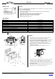
Dimensions (without carrier and cable gland)
70 x 50 x 28 mm
Weight
approx. 150 g
Mounting
DIN rail, wall, tube
Cable clamping range
Ø 3…6 mm
►
NOTICE
* Power supply must be provided not only for ITP11, but also for a sensor. The device voltage drop of 10 V has to be taken into
account.
Fig. 1
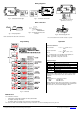
Installation
1. Remove the slide covers (1) in the direction of the arrows (Fig. 2).
2. Unscrew the screws (3) and remove the front panel (2).
3. Screw the cable glands (included) with the sealing rings (5) tightly into
the enclosure, so as to guarantee the IP65 protection.
4. Not used cable entry has to be locked with the blind cap (included).
5. Feed the cable through the cable gland into the enclosure.
6. Connect the wire ends according to the wiring diagrams (Fig. 4 - 6)
and tighten the cap nut (6).
7. Put the front panel (2) back and fasten it with the screws (3).
Fig. 2
Fig. 3
8. To mount the device on DIN rail attach the carrier (7) to the device
using the two screws (4) and snap the device onto the DIN rail.
9. To mount the device on a tube attach the carrier (7) to the tube using
two 6 mm wide cable ties (Fig. 3), then attach the device to the carrier
(7) using the screws (4).
10. To mount the device on the wall use the two holes for the screws (4)
11. Snap the two slide covers (1) onto the front panel (2).
ITP11-W_0217_EN
© All rights reserved. Subject to technical changes and misprints.
akYtec GmbH · Vahrenwalder Str. 269 A · 30179 Hannover · Germany
Tel.: +49 (0) 511 16 59 672-0 · www.akytec.de
Display colour:
R - red
G - green
Enclosure type:
W - universal mounting