ITP11(M04) Process indicator 4-20 mA User guide ITP11(M04)_2018.05_0284_EN © All rights reserved Subject to technical changes and misprints akYtec GmbH · Vahrenwalder Str. 269 A · 30179 Hannover · Germany · Tel.: +49 (0) 511 16 59 672-0 · www.akytec.
Contents 1 Overview ........................................................................................................................................................ 2 2 Specifications ................................................................................................................................................ 2 2.1 Environmental conditions ....................................................................................................................... 2 3 Intended use .
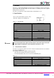
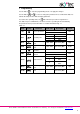
1 Overview The ITP11 is a universally applicable current loop process indicator. It can be connected to any transmitter with 4-20 mA output. The device requires no auxiliary power and is supplied directly from the current loop. The device is designed for control and monitoring of industrial processes. 2 Specifications ITP11 can be ordered in two versions. They differ in the display color. Ordering key: Table 2.
3 Intended use The device may only be used in the manner described in this user guide, properly installed and in accordance with the specification. Damages caused by disregarding the instructions of this manual are without liability. Non-observance of the safety guidelines may result in damage to the device and injury to personal. Improper use Any other use is considered improper.
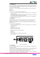
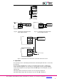
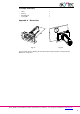
Fig. 5.1 Mounting ITP11 + 1 2 Device with + AO 4-20 mA + Fig. 5.2 Connection to the device with active output 4-20mA ITP11 + Fig. 5.3 Connection to the device with passive output 4-20mA 1 Device with + AO 4-20 mA 2 ... ... ITP11 Power supply + 1 2 + Power supply Fig. 5.4 Connection of 2 or more ITP11 to the one source of 4-20 mA 6 Operation The operating mode is automatically activated if the standard signal 4-20 mA is connected to the terminals.
Filter Undesirable signal fluctuations can be suppressed through the adjustable filter in the parameter td “Filter time constant” (see Fig. 6.1, Table 7.1). The filter time constant can be set within the range 0…10 seconds. The higher the value, the slower the display reaction to changes of the input signal and the lower the susceptibility to interference. The filter is deactivated if td = 0. Fig. 6.1 Square root function This function is intended for transmitters with the square characteristic.
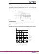
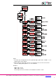
Programming Use the button to enter the programming mode or to apply the changes. Use the buttons and to select or change the parameter. Press and hold the button to activate the ramp function while changing parameter. To return to the operating mode, the button must be pressed for longer than 5 s. If no button is pressed within 20 s, the device reverts to operating mode automatically. The parameter list is presented in Table 7.1 and the flowchart in Fig. 7.1. Table 7.
Fig 7.1 Notes: The minus sign is displayed in the most significant digit, together with 1. If di.P = ---.-, the display range is -99.9...999.9. 2 When setting the signal limits, take into account that in some cases the correct value cannot be displayed though there is no error indication. 1 Example 1: di.Lo: -999 -> 4 mA di.Hi: 9999 -> 20 mA For the input current of 3.9 mA the correct indication should be “-1075”. akYtec GmbH · Vahrenwalder Str. 269 A · 30179 Hannover · Germany Tel.
Example 2: di.Lo: -999 -> 4 mA di.Hi: 9999 -> 20 mA For the input current of 20.8 mA the correct indication should be “10548”. Actually “0548” will be displayed. If the access protection is disabled (PS = oFF), the passcode will be not requested. If the access protection is activated, 0 is displayed. Use the buttons and to enter the passcode 5, then press the button to confirm. If an incorrect passcode is entered, the device returns to the operating mode.
Scope of delivery − − − − ITP11 Gasket Mounting nut User guide 1 1 1 1 Appendix A. Dimensions М22 Ø2 2,5 20,8 Fig. A1 Fig. A2 To prevent the device spinning, the borehole in the front panel must correspond to the dimensions in Fig. A.2. akYtec GmbH · Vahrenwalder Str. 269 A · 30179 Hannover · Germany Tel.: +49 (0) 511 16 59 672-0 · www.akytec.