
Industrial Lawn Mower User Manual


© 2003 Alamo Group Inc.
Section 7 - 3
A-Boom (JD6615 / 7615 Asy Instruction Manual) 07/03
Boom Installation
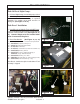
4. Attach the Rod end of the Lift Cylinder
(7) to the Lift Section with Pin (8), Bolt (9) and
Nut (10) (also see Parts Section on the Boom
Assembly) (See Figure 3).
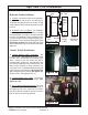
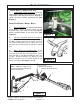
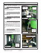
5. Attach the Swing Cylinder . The Swing
Cylinder attaches to the King Post on the Rod
End and to the High frame on the Butt end of
cylinder, There are two holes on the High frame
that cylinder can be connected to. The outer
Hole is the one that cylinder pin should be put
in for a rear swing A-Boom. A Forward Swing
A-Boom is rare, majority wil be rear Swing
(parks to the rear for Transport.) (See Figure
6 & 7).
6. Leave Boom Supported by Hoist untill
Boom is connected to King Post and all cylin-
ders attached. (See Figure 3). The Boom will
have to be lifted again when Head is installed.
Do not lift Boom with Hoist if the Cylinder hoses
are open, the Cylinders are built with the inter-
nal components covered with Oil. If boom is
raised by hoist while these hoses are discon-
nected oil may be forced out of collapsing end
of cylinder.
Boom Installation / Boom Hoses:
(continued)
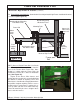
Lifting Lugs weld on here
Figure 5
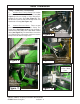
Boom
Retaining Pin
& Nut
Figure 4
Attach Swing
Cylinder to King
Post and High
Frame
Figure 6
Figure 7
Rear
Swing
Hole
High Frame
(Swing Cylinder Mount)
Swing Cylinder
Butt End
Front
Swing
Hole