
Industrial Lawn Mower User Manual

A-Boom (JD 6615 / 7615 Asy Instruction Manual) 07/03
© 2003 Alamo Group Inc.
Section 8 - 8
REMOTE CABLE OPERATION AND INSTALLATION:
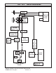
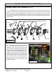
1. Remote operation of the boom movement control valve can be achieved with the use of cables
and remote actuator handles. The remote operation system is standard equipment on cab tractor
units and can be installed on ROPS tractors as well (See Figure 4). Four cable lengths are available
and should be ordered based on the length required to reach from the valve to the Operator’s location
with out binding or kinking. Cable lengths are limited to 48,60,72 and 102 inches.
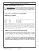
2. To install the cables to the valve, each valve section will require a cable installation kit (4 kits for
a 4-spool valve, 5 kits for a 5-spool valve etc.). Each individual valve connection kit can be ordered
using part number 02971274. Figure 4 displays the contents of each kit. Cables are not included
in Cable Connection Kit.
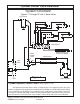
Cylinder Hydraulic Control Circuit: (continued)
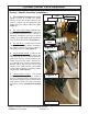
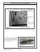
6. Hydraulic Cylinder Hoses. The Hoses for the Hydraulic Cylinders will be marked with bands
that have the Part Numbers on them. These part numbers will vary with the size of the Boom Model.
The 28 ft. model will have more hoses for the Boom Extend Function, the model with the Hydraulic
Door on cutter head willhave more hoses. To find which Hose you have you will need to consult the
Parts / Operators manual. When connecting the Hoses to The Valve use these numbers to connect
the correct hoses to the correct ports. It may be required that you do some tracing of hoses to find
which hose is hooked to which end of a Cylinder. Listed below is a list of which end of Hydraulic
Cylinder should be connected to which Port on valve. (See Figure 2 & 3)
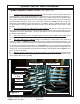
MECHANICAL VALVE MODELS
Cylinder Rod End / Port Base End / Port
Tilt ("B") ("A") Standard
Extend / Door ("B") ("A") Only used with 28' Model or Optional Cutter Door)
Dipper ("B") ("A") Standard
Lift ("A") ("B") Standard
Swing ("A") ("B") Standard
You must consult the Parts Manual to determine correct Hoses used on the Model you have. Also
the type Head used will make the Hose vary. There is a Electrical control valve Option, this will make
a difference of which hose is connected where. If the hoses are connected to the wrong side of valve
it should not damage any thing, it will mean that the control lever function will be reversed or may not
work at all because the Relief Valve is in the wrong direction of Oil Flow to operate.. Changing the
Hoses on the hose ports of the valve will change this.
Cylinder Control Valve Installation