INTERSTATER Assembly Instruction Manual New Holland (Cab or Rops Tractor) TS-100A, TS-115A, TS-125A & TS-135A INTERSTATER Tractors equipped with additional options, special equipment, tractor manufacturer modifications, new tractor models, or Customer alterations may prevent this Mount Kit from being properly mounted to the tractor. Alamo Group is not responsible for modifications to the MountKit to accommodate these differences. ALAMO INDUSTRIAL 1502 E.
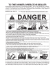
TO THE OWNER/OPERATOR/DEALER All implements with moving parts are potentially hazardous. There is no substitute for a cautious, safe-minded operator who recognizes the potential hazards and follows reasonable safety practices. The manufacturer has designed this implement to be used with all its safety equipment properly attached to minimize the chance of accidents. BEFORE YOU START!! Read the safety messages on the implement and shown in your manual.
INTRODUCTION ABOUT THIS MANUAL: The intent of this publication to provide the competent technician with the information necessary to perform the CORRECT Assembly to the Alamo Industrial Product. This will, in turn provide for complete customer satisfaction It is hoped that the information contained in this and other Manuals will provide enough detail to eliminate the need for contact of the Alamo Industrial Technical Service Dept.
INDEX - ASSEMBLY INSTRUCTION Page Index Introduction..................................................................................... Index 1 General Index................................................................................. Index 2 & 3 User / Assmbly Notes..................................................................... Index 4 Section 1 Pre-Dilivery Check List...................................................................... 1-1 to 1-4 Section 2 Mainframe Assembly...............
INDEX - ASSEMBLY INSTRUCTION Page Section 5 Modify tractor Exhaust system.......................................................... 5-1 to 5-3 Section 6 Tractor Fuel Tank Replacement........................................................ 6-1 to 6-2 Section 7 Wing Mower Installation..................................................................... 7-1 to 7-11 Wing Mower Cut Off Switches.......................................................... 7-1 to 7-5 Wing Mower Hose Connections....................
NOTES Interstater (NH TS-100A , 115A , 125A & 135A Asy. Manual) 06/04 © 2004 Alamo Group Inc.
Section 1 INTERSTATER New Holland TS100A, TS115A TS125A, TS135A Tractor PRE-DELIVERY INSPECTION CHECKLIST Interstater (NH TS-100A , 115A , 125A & 135A Asy. Manual) 06/04 © 2004 Alamo Group Inc.
PRE-DEL INSPECTION CHECKLIST Pre-Operation Inspection: Check the following items before operating the unit to assure that they are properly assembled. (See following page 1-4 for component location) Saftey Equipment: ___ ___ ___ ___ ___ ___ ___ Operators Manual is with Unit. The Safety Decals are installed as listed in the Assembly Manual. Valve operation plate is installed.
PRE-DEL INSPECTION CHECKLIST Pre-Operation Inspection: Check the following items before operating the unit to assure that they are properly assembled. (See following page 1-4 for component location) Tractor Mower Operation Inspection: Using all Safety precautions, operate the Tractor and Mower unit for 30 minutes and while the unit is running check the following items: Note! Only make adjustments after the mower has been turned off and all motion has stopped and all hydraulic pressure has been relieved.
Tractor - Mower Component Location Check List Pumps, Hyd. Tank & Cover Right Wing Flail Left Wing Flail Rear Center Flail Interstater (NH TS-100A , 115A , 125A & 135A Asy. Manual) 06/04 © 2004 Alamo Group Inc.
Section 2 INTERSTATER New Holland TS100A, TS115A TS125A, TS135A Tractor Main Frame Asy. Interstater (NH TS-100A , 115A , 125A & 135A Asy. Manual) 06/04 © 2004 Alamo Group Inc.
Main Frame Dual / Single Wing Prepare Tractor: Remove Components from Tractor. There are items that must be removed from tractor that will not be used before the mainframe can be mounted. On each side of the tractor there heavy mounting lugs that are bolted to the tractor frame. One on the left hand and one on the right hand side. The steps on the left and right side has to be removed.
Main Frame Dual / Single Wing Mount Frame Rails To Tractor: Frame Mounting Rails LH Side 2. Install the Main Frame. The Mainframe bolts up under the Tractor from the bottom. Bolt the Hyd Tube Assembly to the mainframe before sliding it up under the tractor (See Figure 2 & 3), make certain that the hyd tube assembly is bolted in the right direction as shown in Figure 2 as the tubes must be installed correctly for the hydraulic lines to be installed correctly later.
Main Frame Dual / Single Wing Mount Frame Rails To Tractor: 5. Install LH Wing Lift frame. The wing lift frame pivots on two hinge pins. When installing these pins they must be aligned in a way that will allow the retaining bolt to be installed. The Right side and the Left side will install in the same way (See Figure 7 & 8) 6. Install Lift Cylinder Mount Weldment . The lift cylinder mount is a bolt on weldment that bolts to the main frame with four bolts.
Main Frame Dual / Single Wing Prepare 4 Spool Control Valve: 1. Remove standard control Handles. When using the remote control cables and handles the standard handles must be removed and discarded. This is done by removing the C-Clips and pins that hold the handles to the valve body and the C-clips and pins that hold handles to the spools. (See Figure 12) 2. Bolt Valve Mounting Bracket to Mainframe . The valve mounting bracket is bolted to the Right Hand side of the tractor.
NOTES Interstater (NH TS-100A , 115A , 125A & 135A Asy. Manual) 06/04 © 2004 Alamo Group Inc.
Section 3 INTERSTATER New Holland TS100A, TS115A TS125A, TS135A Tractor Pump, Driveshaft & Hyd. Tank Interstater (NH TS-100A , 115A , 125A & 135A Asy. Manual) 06/04 © 2004 Alamo Group Inc.
Pump & Driveshaft Schematic Hyd Pump (Cyl Circuit) Drive Belt Driven Pulley Shield 123 123 Pulley Adapter Mounting Bolts Locknut Tractor Engine Pulley 123456 123456 123456 Mounting Bolt & Washer * Bearing Collar Driveshaft ** Pump Mount Plate Drive Pulley & Splined Sleeve Weldment Pulley Adapter * Driveshaft Bearing ** Small (Cyl Hyd) Pump Mount Plate mounts here Tandem Pump for Dual Wings Pump Mount Weldment 123 123 123 123 Left Wing Pump 123456 123456 123456 Right Wing Pump Figure 1 I
Pump - Driveshaft - Hyd tank Install Driveshaft, Pump & Tank: Air After-Cooler 1. Gain Access to Tractor Engine. Raise the hood of the tractor to revel the tractor engine (See Figure 2). Remove the engine guards on the left hand side of tractor (See Figure 3). This will allow you access to the Tractor Crankshaft Pulley. (See Figure 1). Remove the plate under After cooler which will make installing driveshaft easier. Cover removed Tractor Bolster 2. Bolt Pulley Adapter to Engine Crankshaft Pulley.
Pump - Driveshaft - Hyd tank Install Driveshaft, Pump & Tank: (continued) Use Flatwasher here 10. Small Pump Belt Adjustment. The belt Guard is retained with the same bolts that mount the pump plate and the same bolts that are used to adjust the drive belt. For now do not install the belt guard. Snug these bolts for now but do not tighten them 11. Align driven pulley. The driven pulley on the small pump will need to be aligned with the drive pulley below it.
Pump - Driveshaft - Hyd tank Install Driveshaft, Pump & Tank: (continued) 15. Connect Pump Case Drain To Tank. On the Right Hand side of the tandem pump there will be two small elbows, these are the case drains for the pumps. On the side of the tank and above theses elbows there will be two small plugs screwed into tank. Remove these plugs and install the pipe thread end of the two small hose after coating the threads with pipe sealer.
Pump - Driveshaft - Hyd tank Install Driveshaft, Pump & Tank: (continued) Pressure Hose to RH Wing Motor with Red Plastic Tie 17. Connect Motor Pressure Supply Hoses to Pump. The Tandem Pump has two pressure hoses. The Rear (closest to Tractor Engine) it the supply for the RH Wing Motor. The Outer Pump is the LH Wing Motor Pressure Supply. The hose for the RH Wing should be marked with a red plastic tie on it, the other hose is not Identified. Connect these two hoses at the pump now.
Pump - Driveshaft - Hyd tank Install Driveshaft, Pump & Tank: (continued) 20. Change Straight Bulkhead fitting to an Elbow Fitting. There is a straight bulkhead fitting installed into main frame crossmember that should be changed to a 90 " elbow< (See Figure 14,15,16 & 17). Remove this Straight Bulk Head Fitting & Replace it with an Elbow 21. Connect Motor Pressure Supply Hoses to Main Frame Cross Member. The Tandem Pump has two pressure hoses.
Pump - Driveshaft - Hyd tank Install Driveshaft, Pump & Tank: (continued) Tank Return Filter Pipe Tee Reducer Fittting 23. Install Hose Fittings into Return Filter in Tank. There is a return filter in the top of the RH side of tank. In the end of the filter housing install a Tee Fitting with an Elbow in it, the tee fitting should point outward as seen in figure 19. In the end of the Tee there will be reducer to allow the installing of a smaller hose.
Pump - Driveshaft - Hyd tank Install Driveshaft, Pump & Tank: (continued) 26. Install the small pump pressure hose to pump. The pressure hose connects to the RH side of the small pump and is run down the RH side of the frame with the return hoses (See Figure 21) 27. Install sleeving over the return hoses from heads and control valve and Control valve Pressure Hose. Slide the three hoses through the sleeving.
NOTES Interstater (NH TS-100A , 115A , 125A & 135A Asy. Manual) 06/04 © 2004 Alamo Group Inc.
Section 4 INTERSTATER New Holland TS100A, TS115A TS125A, TS135A Tractor Remote Control Cable Connections Interstater (NH TS-100A , 115A , 125A & 135A Asy. Manual) 06/04 © 2004 Alamo Group Inc.
Remote Control Cable Connections Remote Control Cable Connections Cab Tractor: 1. Control Valve Cable Clips. Locate the four cable mounting clips and four roll pins (shown laying on muffler bracket for illustration only in Figure 1). Start the roll pins into the clips as shown through one side only (See Figure 1). Insert the Remote Cable through the Control Valve Mount Bracket (See Figure 2). Install the large cable retaining / Adjusting nut onto threaded portion of cable housing (See Figure 2).
Remote Control Cable Connections Remote Control Cable Connections: (continued) Figure 4 Figure 5 8 7 4 1 5 2 6 3 Figure 6 Figure 7 Vent Plug Control Valve Hoses 2 3 1 Figure 8 Figure 9 Interstater (NH TS-100A , 115A , 125A & 135A Asy. Manual) 06/04 © 2004 Alamo Group Inc.
Remote Control Cable Connections (Cab Tractor) Remote Control Cable Connections Cab Tractor: 1. Install Remote Cable Control Lever Mounting Bracket In Cab Tractor. Locate the four existing threaded holes that are in the RH side on the cab door post (See Figure 10). The Control Lever Mounting bracket will bolt to two of these holes. Align the matching holes of the mounting bracket with two of the threaded door post holes. Install the two mounting bolts through bracket and into door post (See Figure 11) 2.
Remote Control Cable Connections (Cab Tractor) Remote Control Cable Connections Cab Tractor: (continued) 4. Install Wire Harness through floor and boot. The Wire harness will come to you with the on / off switches attached, these switches will need to be removes to Push the Wire Harness up through the floor and boot cover (See Figure 15 & 18). Screw the cover to the Rubber Floor Mat with the screws furnished. 5. Insert Cables up through Boot Cover.
Remote Control Cable Connections (ROPS Tractor) Remote Control Cable Connections ROPS Tractor: 1. Install Valve Stand to Tractor on ROPS Tractor only. Attach Valve Stand to the top of the Right Lift Cylinder Support with (3) 1/2" x 1-1/2" bolts, and (3) 1/2" locknuts (See Figure 19). 2. Attcah Valve Stand to Valve Mount Bracket. Attach Valve Stand to the Valve Mount Bracket with (2) 3/8" x 1-1/4" bolts and (2) 3/8" locknuts (See Figure 20). 3. Attach Control Valve to the Valve Stand.
Remote Control Cable Connections Remote Control Cable Connections: (continued) Tractor Front 6. Each controller assembly comes fully assembled. All required hardware etc. is included. The control cables are not included with the control handles and should be ordered separately. The Controller must face forward as shown or controls will be backward (See Figure 23) 7. To attach the cable, manipulate the controller handle so that the attachment nut is exposed as shown.
Remote Control Cable Connections Remote Control Cable Connections: (continued) 12. Adjust Handles. The handles will have some adjustment to the as the Mounting bracket the handles bolt to will have slotted holes to allow the handles to be rotated to position the handles straight up. (See Figures 11, 26 & 27) Cab Model Shown. 13. Tie Cables and Wire Harness together. Tie the cables and Wire Harness together with plastic ties inside the cab and outside the cab. This will keep them from moving around.
Remote Control Cable Connections Remote Control Cable Connections: (continued) 15. Adjust Handles. Handles for thr Cab Model or Rops Nodel will adjust about the same.The handles will have some adjustment to them as the retaining nut on the Valve end of the cable is tightened. Tighten these retaining nuts now. (See Figure 28). 16.
Wire Harness Connections Wire Harness Connections: Wire Harness Wires Tractor Starter 1. Connect Wire Harness to Tractor Starter. The wires to the starter from the off on switches will need to be connected to the tractor near the started connections (See Figure 30, 31 & 32). All see the wire / harness schematic on the following pages. Consult the Tractor Repair Manual for wiring schematic of Tractor. Figure 30 2. Check all Wire Harness Routing.
Wiring Harness Schematic Figure 32 Right Switch Left Switch DOUBLE WING MOWER SHOWN (Single Wings have only the Right Wing Motor Solenoid Valve harness) Brown Brown Red 3 Terminal Connector Black Cavity Plug Left Wing Motor Solenoid Valve Right Wing Motor Solenoid Valve White Black/Wht Yellow Black/Wht Yellow Fuse Red Left Switch Red Right Switch Brown White Yellow Brown (Start Terminal) Brown (Starter Solenoid) 3 Terminal Connector Red (to Accessory Terminal) Black (Ground @ Tractor Start
NOTES Interstater (NH TS-100A , 115A , 125A & 135A Asy. Manual) 06/04 © 2004 Alamo Group Inc.
Section 5 INTERSTATER New Holland TS100A, TS115A TS125A, TS135A Tractor Tractor Exhaust Modification Interstater (NH TS-100A , 115A , 125A & 135A Asy. Manual) 06/04 © 2004 Alamo Group Inc.
Tractor Exhaust Modification Modify Exhaust on Tractor: Stock Exhaust Pipe to Turbo Components 1. Modify Tractor Factory Exhaust System. The Exhaust of the tractor must be modified to move exhaust (muffler) in closer (8-1/ 2" Closer) to the hood of tractor to give the Interstater clearance when wing is folded into the transport position. This should be done before the wing mower is mounted. 2. Remove Old Exhaust System.
Tractor Exhaust Modification Modify Exhaust on Tractor: (continued) 6. Install Exhaust Mount Bracket. The new Exhaust mounting Bracket Weldment (See Figure 4 & 5 P/N 02980649) must be installed to mount the new Turbo Downpipe to using the 3-1/ 2" Clamp (P/N 02959132) to mount the Downpipe the new Exhaust mounting bracket. Note: The New Exhaust Bracket has slotted holes in it that are not shown in the angle that figure 4 is showing the weldment. There are 3 Bolts and lockwashers used to mount this weldment.
NOTES Interstater (NH TS-100A , 115A , 125A & 135A Asy. Manual) 06/04 © 2004 Alamo Group Inc.
Section 6 INTERSTATER New Holland TS100A, TS115A TS125A, TS135A Tractor Tractor Fuel Tank Replacement Interstater (NH TS-100A , 115A , 125A & 135A Asy. Manual) 06/04 © 2004 Alamo Group Inc.
Manufactured Fuel Tank Installation Tractor Fuel Tank Replacement: 1. Remove the New Holland Factory Fuel Tank From Tractor. Drain all the fuel from the fuel tank with an approved pump or other device. Store fuel in an approved area. Remove the factory fuel tank. It is somewhat easier if the left rear tire & wheel are removed but it is not required.
Section 7 INTERSTATER New Holland TS100A, TS115A TS125A, TS135A Tractor Wing Mower Installation Interstater (NH TS-100A , 115A , 125A & 135A Asy. Manual) 06/04 © 2004 Alamo Group Inc.
Wing Mower Installation Wing Cut Off Switch: 1. Assemble Brackets & Magnetic Switches. Locate the Magnetic switch mounting bracket, dual wings there will be two of these (See Figure 1). If Dual wings the two brackets will have the switches mounted on the opposite side (See Figure 2). Once these have the switches bolted on lay the brackets aside for now. (See Figure 20) Small Screw Hole Slotted Hole for switch wires Bracket Mounting Holes 2. Assemble Magnetic Switch Activators.
Wing Mower Installation Wing Cut Off Switch: (continued) 4. Install Mower Rear Mounting Brackets & Magnetic Switches. The Mower Hinge Link has a LH & RH (See Figure 7). These brackets will slide over the Hinge Pin which is bolted to the mower deck at the factory. There are two Threaded holes in the end of the hinge pin (See Figure 7) These two holes serve dual purpose. First they hole the hinge bracket on and the Magnetic Activator Bracket on.
Wing Mower Installation Wing Cut Off Switch: (continued) 5. Install Mower Front Mounting Brackets. The Mower Hinge Front Bracket has a has a LH & RH (See Figure 10). These brackets will slide over the Hinge Pin which is bolted to the mower deck at the factory. This bracket will be bolted to the Lift frame with four bolts. This hinge Pin WILL NOT have threaded holes as the rear hinge pin did. LH Wing Shown From Front 6. Install Wing Mower to Lift Frame.
Wing Mower Installation Wing Cut Off Switch: (continued) 10. Connect Tilt Cylinder to Mower Deck. The Tilt Cylinder connects to the mower head (See Figure 15 & 16). Note you will need to remove the belt guard to connect this cylinder so you will have room for the cylinder mounting pin to be installed (See Figure 16). When connecting the cylinder the grease fitting on the rod end must face up, the locking collar on the cylinder must face up and be tightened on rod end.
Wing Mower Installation Connecting Mower Motor Hoses: 1. Connect Motor Pressure & Return Hoses to Mower Deck. Connecting the Motor Hoses is very critical that they a re connected to the correct fittings, If these hose are connected backwards it will damage the cooling tubes on the deck, the cooling tubes cannot take the pressure it will make them swell up and bulge. IMPORTANT FACT.
Wiring Schematic Figure 21 Right Switch Left Switch DOUBLE WING MOWER SHOWN (Single Wings have only the Right Wing Motor Solenoid Valve harness) Brown Brown Red Black 3 Terminal Connector Cavity Plug Left Wing Motor Solenoid Valve White Black/Wht Right Wing Motor Solenoid Valve Yellow Black/Wht Yellow Fuse Red Left Switch Red Right Switch Brown White Yellow Brown (Start Terminal) Brown (Starter Solenoid) 3 Terminal Connector Red (to Accessory Terminal) Black (Ground @ Tractor Starter) White
Pump & Motor Hydraulic Schematic TRACTOR REAR Return to Tank from Wet Tubes of RH Wing Return to Tank from Wet Tubes of LH Wing RIGHT WING T OU Return Line Tee LEFT WING Mainframe Tube Cross Over Hose Sleeving OUT Hose Sleeving IN IN Pressure from Pump to RH Wing Motor OUT Pressure from Pump to LH Wing Motor TRACTOR LH SIDE TRACTOR RH SIDE Return to Tank from Wet Tubes of RH & LH Wing Figure 22 IN Indicates Direction of Flow IN Hose Sleeving Pressure from Pump to RH Wing Motor TRACTOR
Pump & Motor Hydraulic Schematic LEFT WING HYDRAULIC MOTOR SHOWN Case Drain from Motor to Motor Valve Return from Motor to Rear Wet Tube and on to Tank NEVER CONNECT HIGH PRESSURE HOSE TO WET TUBES ON DECK ! High Pressure from Pump to Motor Return from Front Wet Tube to Tank Figure 23 RH Wing Pump Case Drain LH Wing Pump Case Drain Tandem Pump, Inner Pump for RH Wing & Outer Pump for LH Wing RH Wing Pump High Pressure Line Hose Sleeving Tandem Pump LH Wing Pump High Pressure Line LH Wing Pump Suction
Pump & Motor Hydraulic Schematic Tank Return Filter Assembly & Tank Return Pressure Gauge Tank Return Hose from Cylinder Control Valve to Tank Tank Return Hose from Wet Tubes on LH & RH Wing Decks Oil Level Sight Glass Oil Temperature Gauge Figure 25 Upper Connection Always from Pump To Wing Motors NEVER TO WET TUBES (HIGH PRESSURE) Main Frame Cross Over Bracket & Tubes (RH Side Shown, note Tee Fitting in lower fittings Lower Connection Always from Deck Wet Tubes to Filter Tank Return Line (LOW PRESSURE
Pump & Motor Hydraulic Schematic Wings have a front and a rear wet tube for cooling the oil. At the outer end of the decks there is a cross over hose which allows the oil to cross from the rear tube to the front tube,The Tubes and the cross over hose are in the oil return to tank circuit which has to be low pressure.. Figure 27 Interstater (NH TS-100A , 115A , 125A & 135A Asy. Manual) 06/04 © 2004 Alamo Group Inc.
NOTES Interstater (NH TS-100A , 115A , 125A & 135A Asy. Manual) 06/04 © 2004 Alamo Group Inc.
Section 8 INTERSTATER New Holland TS100A, TS115A TS125A, TS135A Tractor Rear Mower Installation Interstater (NH TS-100A , 115A , 125A & 135A Asy. Manual) 06/04 © 2004 Alamo Group Inc.
Rear Three Point Mower Rear Three Point Mower Connection: 1. The Rear Mower is a standard Three Point Hitch mounted mower that is PTO driven through a driveline. It will be sent already assembled with the driveline tied to it. (See Figure 1) 2. Connect Lower Hitch Pins. The lower hitch pins connect to the lift arms of the tractor with click pins, these pins are furnished with the mower. (See Figure 2). It is best to connect the lower arms of the three point first.
Rear Three Point Mower Rear Three Point Mower Connection: 5. Leveling the Rear Mower & Adjust gutting Cutting Height. The Rear Mower is leveled with the top Three Point Link. The Cutting Height is adjusted by moving the Roller up or down by change the bearing bracket mounting hole. The is a decal on the deck next the Operators/ parts manual cannister (See Figure 5 & 6) 6. Rear Mower Completly Connected. With the rear mower completly connected.
Rear Three Point Mower Rear Three Point Mower Connection: 8. Slip clutch is incorporated in the PTO driveline. It is designed to slip, absorb the shock load, and protect the driveline. After the first hour of operation, the slip clutch should be checked for overheating. After this first check, the slip clutch should be checked weekly or anytime there is overheating. To adjust the slip clutch, tighten the spring bolts 1/8 (maximum) turn at a time.
Lubrication Points LUBRICATE ALL POINTS BEFORE OPERATING MOWER FIRST TIME A B C D E F Lift Frame Pivot Pin Wing Mower Belt Idler Arm Cuttershaft Bearings TIlt Cylinder Rod Ends Lift Cylinder Rod Ends Roller Bearings G H J K L Figure 9 Interstater (NH TS-100A , 115A , 125A & 135A Asy. Manual) 06/04 © 2004 Alamo Group Inc.
Initial Start-Up Procedure INITIAL START-UP PROCEDURE: 1. 2. 3. 4. 5. 6. Check all nuts and hex head capscrews to ensure all are tight and all lock washers are fully compressed (flattened). Check all hoses and hydraulic connections. Make certain they are secure. Inspect all moving parts and besure that no wires or hoses will be caught or pinched when the tractor or the INTERSTATER is in operation. Tie down loose wires and hoses.
Initial Start-Up Procedure CAUTION ROTATING KNIVES! Remove all foreign objects and stand clear of cutter units. DO NOT GET NEAR! NOTE: On tractor hydraulic powered circuit only, make certain that there is full flow from tractor hydraulic system to control valve. Refer to tractor manual. 9. After hydraulic system is fully charged and functioning properly, switch cutter units on, then speed engine up to 540 RPM PTO speed. Maintain this speed for about 5 minutes.
NOTES Interstater (NH TS-100A , 115A , 125A & 135A Asy. Manual) 06/04 © 2004 Alamo Group Inc.
Section 9 INTERSTATER New Holland TS100A, TS115A TS125A, TS135A Tractor Mounting Specifications & Mount Kit Numbers Interstater (NH TS-100A , 115A , 125A & 135A Asy. Manual) 06/04 © 2004 Alamo Group Inc.
Tractor / Mower Mounting Specifications New Holland TS100A Cab/2wd As of: 4-16-04 10.00-16 Max Front Tire 18.4-30 Max Rear Tire Mainframe: Right Hand Only (5" Offset Right) ………………....................02981068 Comp Crate: RH Only w/Aux Pump ………………………….................... 02981075 Mainframe: Dual Wing (5" Offset Left & Right) …….....……..................... 02980935 Comp Crate: Dual Wing w/Aux Pump ……………………….....................02980823 Replacement Fuel Tank (46 gal/Req’d for Dual) ………………................
Tractor / Mower Mounting Specifications New Holland TS100A ROPS/2wd As of: 4-16-04 10.00-16 Max Front Tire 18.4-30 Max Rear Tire Mainframe: Right Hand Only (5" Offset Right) ………………... 02981068 Comp Crate: RH Only w/Aux Pump …………………………....02981072 Mainframe: Dual Wing (5" Offset Left & Right) …….....…….... 02980935 Comp Crate: Dual Wing w/Aux Pump ……………………….... 02980919 Replacement Fuel Tank (46 gal/Req’d for Dual) ……………... 02980938 Options: Lift Chain Kit (See Spec Below) ……………………………......
Tractor / Mower Mounting Specifications New Holland TS115A/125A/135A Cab/2wd As of: 5-19-04 10.00-16SL (F-2) Min / 12.4-24 (R-1) Max Front Tire 18.4-30 (R-1W) Max Rear Tire Mainframe: Dual Wing (5" Offset Left & Right) …….....……....... 02981078 Comp Crate: Dual Wing w/Aux Pump ……………………….........02981009 Comp Crate: Dual Wing w/Tractor Hyd …………………….......... 02981087 Replacement Fuel Tank (46 gal/Req’d for Dual) …………….....… 02980938 SPECIAL ORDER: For tractors with oversized tires (Ref: 14.9-24 Frt / 18.
Tractor / Mower Mounting Specifications Continued From Previous Page 10. The driveline for these models was designed on a TS115A. Because the TS125A & 135A are equipped with a different crankshaft pulley, some modification to the length may be necessary. However, the pulley adapter should fit all models without any problem. Keep in mind that until a TS125A or 135A is mounted at our Seguin facility, any necessary driveline modifications must be made at the dealer/customer’s expense. 11.
NOTES Interstater (NH TS-100A , 115A , 125A & 135A Asy. Manual) 06/04 © 2004 Alamo Group Inc.
Insterstater Assembly Manual New Holland TS-100A,115A, 125A & 135A 2004 Edition P/N 02981188 iInterstater (NH TS-100A ,115A, 125A & 135A Asy. Manual) 06/04 © 2004 Alamo Group Inc.