Distribuitor: CALOR SRL Str. Progresului nr. 30-40, sector 5, Bucuresti tel: 021.411.44.44, fax: 021.411.36.14 www.calorserv.ro - www.calor.ro ACK2 OIL/GAS FIRED HOT WATER BOILERS ACK2-80 ....... ACK2-3000 INSTALLATION, AND COMMISIONING MANUAL Rev B : Feb.
INDEX 1 INTRODUCTION ……………………………………………………… 2 2 WARNINGS …..……………………………….…………………….…. 2 3 DECLARATION OF CONFORMITY …………………………..……. 4 4 GUARANTEE AND SERVICE ………………………………………. 4 5 GENERAL SPECIFICATIONS ……………………………………… 5 6 OPERATING PRINCIPLES …………………………………………. 5 7 MAIN PARTS ………………………………………………………….. 6 8 INSTALLATION ……………………………………………………….. 7 8.1 SAFETY ARRANGEMENTS ……………………………………. 8 8.1.1 MINIMUM SAFETY EQUIPMENT REQUIRED FOR SEALED SYTEMS ………………….. 8 8.1.
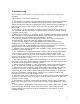
1 INTRODUCTION This manual comprises the information concerning the Installation, operation, use and maintenance of ACK2 hot water boilers. This manual alone is not sufficient for correct installation, operation and use, installers, services and user must obey the rules specified in current EN + local norms, EC directives and local codes. This manual gives supplementary information and precautions. Keep this booklet near the appliance in a safe place in the boiler room for future reference.
Boilers must not be installed in areas where inflammable vapors and materials are likely to e present. To avoid damage to the boilers, contamination of the combustion air by high levels of dust or halogenated hydrocarbons (e.g. Solvents, spray can propellants, cleaning agents, adhesives, etc.) must be avoided. The humidity level must not be high in boiler rooms.
3 DECLARATION OF CONFORMITY We hereby make the fallowing declaration with regard to the appliance trademark ACK2, models ACK2-80, ACK2-100, ACK2-125, ACK2-150, ACK2-200, ACK2-250, ACK2-300, ACK2-350, ACK2-400, ACK2-500, ACK2-600, ACK2-700, ACK2-800, ACK2-900, ACK2-1000, ACK2-1250, ACK2-1500, ACK2-1750, ACK22000, ACK2-2500, ACK2-3000.
5 GENERAL SPECIFICATIONS ACK2 boilers are reverse flame, 2 pass, wet back, cylindrical shell type, hot water, liquid or gas fired, B 23 steel boilers. They are manufactured and tested in accordance with TS EN 303-1, by an ISO 9001-2000 registered company. They are economical and environmentally friendly. Compact design ensures easy transport into boiler rooms. The boilers have been specially designed and produced to perform efficient combustion with both gas and liquid fuels.
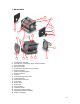
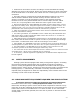
MAIN PARTS 20 4 2 1 9 7 19 12 15 18 11 13 14 20 5 10 1234567891011121314151617181920- 16 17 3 8 6 Combustion chamber. Second pass combustion pipes and turbulators. Main boiler body. Two way hinges. Combustion chamber door insulation. Boiler front door Flame monitoring glass. Boiler insulation. Flue box Functional explosion cover. Supporting feet. Gas/liquid fuel burner.
INSTALLATION The installation of the boilers must be performed according to the current local standards and in addition, instructions stated below; All installation, assembly and maintenance work must be carried out exclusively by fully trained, professionally qualified personnel and must conform with this manual and the local codes and requirements of the authority having jurisdiction, or in the absence of such requirements, apply to the EEC directives and European norms (EN).
All electrical connections must be according to current standards and wiring diagrams are given in this manual. Please pay special attention to earth connections to all electrical items in the boiler room. Never use fuel or water pipes as an earth connection. The boiler chimney connections should be designed according to the norms and the distance between boiler and the chimney must be minimum.
Protection against exceeding the maximum operating pressure; Each boiler shall be served by at least one safety valve in order to protect the system against exceeding the maximum operating pressure. The safety valve is not a standard supply with the boiler, it must be fitted by the installer on the flow line of the boiler without any isolation valve or similar items and they must confirm prEN 1268-1 with a minimum size of DN 15.
Devices for controlling the operation temperature to adapt the heat supply to the heat demand. The maximum set-point of the temperature controller shall not exceed the maximum operating temperature of the boiler. Pressure maintaining control device to ensure the required minimum operating pressure of the system. This can be achieved for example by an automatic refill-set or expansion vessel linked to a low pressure limiter.
Operational requirements of open vented systems; In order to maintain a safe and economical operation, open vented heating systems shall be equipped with: Water level indicator Temperature indicator (% 20 higher then the operating temperature and mounted in the flow pipe of the system) Devices for controlling the operation temperature to adapt the heat supply to the heat demand. The maximum set-point of the temperature controller shall not exceed the maximum operating temperature of the boiler.
8.4 FLUE GAS EXHAUST SYSTEM. ACK2 boilers are B 23 type appliance so the flue gases must be connected to an adequate draught chimney, without any flue gas leakage to the boiler room. Chimney design must be according to local codes. Chimney inside diameter, height, material, thermal insulation, strength shall be according the flue gas specifications and shall not cause dangerous high pressures. 0 to -0.3 mbar vacuum shall be observed at the flue gas exit of boiler.
Note :During boiler economic life, the total make up water volume can not be more then 3 times of the total system water. Guarantee will not be valid, if the boiler is out of service because of corrosion, sludge formation and deposits In order to prevent corrosion special care needed for oxygen infusion to the heating system water side. Possible points for oxygen infusion are from open vented cisterns, negative pressure points on the system and some gas permeable system items like plastic pipes.
Before firing the burner, be sure that system is full of water and all control items are set to desired value and working properly. Check the fuel pressure, temperature and fuel line leakages before running the burner. Run the burner and adjust it to proper output according to boiler needs. Analyze the flue gas and be sure that emission levels of CO, NO x , soot, CO 2 or O 2 are according to current regulations.
10 ANEX - 15 -
HS HS V V V SP V 3W V SP V V V TC TI PI LV HS SP ACP MET 3W V TCL TC TI PI SPL1 SPL2 SV FT LV PR CV ARFS DV ACP PI V TCL V SPL2 PI SV FT SPL1 V LV MET Heating system Circulation pump Anti condensate pump Membrane expansion tank Three way valve High Limit themostat Boiler thermostat Thermometer Pressure gauge Max. Safety pressure limiter Min.
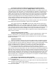
OEC V HS HS V V V SP V 3W V SP V V V TCL TC TI V BPP V BOILER WLI LV TI HS Heating system SP Circulation pump BPP OEC By pass pump Open expansion cistern 3W V Three way valve TCL High Limit themostat TC TI Boiler thermostat Thermometer WLI Water level indicator LV Lockable valve V Valve PR Pressure regulator CV One way valve ARFS Automatic refill system DV Drain valve V V DV V PR CV V ARFS TYPICAL SAFETY EQUIPMENT AND HYDROULIC ARRANGEMENT FOR OPEN VENTED (OPE
150 100 BOILER FEET WIDTH 100 80 BOILER FEET LENGHT 80 - BOILER FOUNDATION SHALL BE ENOUGH STRENGHT TO CARRY THE BOILER FULL WITH WATER AND ACCESSORIES - BOILER FOUNDATION SHALL BE FROM NON CONBUSTIBLE METERIALS - BOILER FOUNDATION SURFACE SHALL BE LEVEL AND SMOOTH - BOILER FOUNDATION 18
D B W W W L A 500 A L+600 A : Burner lenght. B : 600 mm minimum. W : A + 200 mm minimum. D : L/2 + 500 (min 600 mm) L : Lenght of boiler. H : Height of the boiler room must be minimum 1000 mm heigher then the boiler height. Note : These dimensions are recomendations only. They can be changed according to local standarts.
FOR CIRCULAR CROSS SECTION (SCHIEDEL) 3500 3000 850 800 700 750 600 650 550 2500 500 NOMINAL OUTPUT (kW) 2000 1750 1500 450 400 1250 1000 900 800 700 600 500 450 400 350 300 350 300 250 250 225 200 175 150 220 200 Inside diameter 180 125 100 90 80 70 60 50 40 160 20 10 0 5 10 15 20 25 30 35 40 45 50 55 60 EFFECTIVE CHIMNEY HEIGHT (m) 20
21
FOR SQUARE CROSS SECTIONS (PLEWA) 55x55 70x70 60x60 3500 3000 2500 50x50 45x45 40x40 2000 1750 1500 35x35 30x30 NOMINAL OUTPUT (kW) 1250 1000 900 800 700 600 500 450 400 350 300 250 225 200 175 150 125 100 90 80 70 60 50 40 30 20 10 27.5x27.5 25x25 22.5x22.
ACK2 OIL/GAS FIRED HOT WATER BOILERS ALARKO - GAS BURNER SELECTION CHART Boiler Net Heat Gross Heat Back pressure Burner type Burner exploitation Percentage Blast tube Length Required. Length Diameter (Boiler) Diameter (Burner) ø ø mm Standard (S) blast tube (mm) Boiler opening for burner (mm) Burner blast tube (mm) Combustion chamber diameter mm Combustion chamber length mm Combustion chamber Volume (m3) Thermal load (kW/m3) 130 108 339 950 0,0857 1.
ACK2 OIL/GAS FIRED HOT WATER BOILERS LAMBORGHINI - GAS BURNER SELECTION CHART Boiler type Net Heat Gross Heat Back pressure Burner type Burner exploitati on Percenta ge Blast tube Length Required.
ACK2 OIL/GAS FIRED HOT WATER BOILERS ALARKO - OIL BURNER SELECTION CHART Boiler Net Heat Gross Heat Back pressure Burner type Burner exploitation Percentage Blast tube Length Required. Length Standard (S) blast tube (mm) Diameter Diameter ø ø Boiler opening for burner (mm) Burner blast tube (mm) Combustion chamber diameter mm Combustion chamber length mm Combustion chamber Volume (m3) Thermal load (kW/m3) 130 339 950 0,0857 1.
ACK2 OIL/GAS FIRED HOT WATER BOILERS CIB UNIGAZ - GAS BURNER SELECTION CHART Burner exploitati on Percenta ge Blast tube Lengt h Requir ed. Length Diameter Diameter ø ø Standard (S) blast tube (mm) Boiler opening for burner (mm) Burner blast tube (mm) Combustion chamber diameter mm Combustion chamber length mm Combustion chamber Volume (m3) Thermal load (kW/m3) 150 180 130 108(113) 339 950 0,0857 1.190 99 150 180 130 108(113) 339 950 0,0857 1.493 M-.AB.S.IT.A.0.
ACK2 OIL/GAS FIRED HOT WATER BOILERS CIB UNIGAZ - OIL BURNER SELECTION CHART Burner exploitati on Percenta ge Blast tube Lengt h Requir ed. Length Length Diameter Boiler Net Heat Gross Heat Back pressure type (kw) (kw) (mbar) type model % mm Minim um Standard (S) blast tube (mm) Extended (L) blast tube (mm) blast tube (mm) Combustion chamber diameter mm Combustion chamber length mm Combustion chamber Volume (m3) Thermal load (kW/m3) ACK2-80 93 102 0,5 G10 G.TN.L.IT.
TECHNICAL SPECIFICATIONS OF ACK2 TYPE BOILERS Range of Temperature Control °C 55-90 Boiler Type Hot Water, Two Pass, Reversal Flame, Steel, B Fuel Type Oil (6 cST at 20 °C) 23 Gaseous (Natural Gas, Town Gas, LPG) Nominal Output °C 170-190 Partial Output °C 120-140 mbar -0,3~0 Exit Flue Gas Temperature °C Required Draught Specifications Unit BOILER TYPE ACK2-250 ACK2-300 ACK2-350 ACK2-400 Combustion Chamber Pressure mbar 0,5 0,6 0,8 1,2 1,5 1,6 1,4 2 2,2 2,1 Exit Flue Gas Ma
BOILER CONTROL PANELS 1 2 3 5 1 2 1 2 3 5 4 3 5 4 6 Boiler Control Panel Device Functions : 1. Main switch : Energize or shut off the panel 2. Safety limit thermostat: If boiler water temperature is out of control (boiler thermostat are not functioning, electric wire fault, etc) and reaches 100 °C (+/- 5 °C) it will stop the burner immediately. It is manual reset type high temperature safety device. It will not reset automatically before reset it find the reason for high temperature. 3.
BOILER CONTROL PANEL WIRING DIAGRAMS G EL LT T1 MS L N 1 2 L N C 3 4 5 RT F L N 220/230 V (AC) 50 Hz - 16 A (max) BURNER LT EARTHING T1 2 1 T2 G MS L N 1 2 L N RT F L N 220/230 V (AC) 50 Hz - 16 A (max) MS : MAIN SWITCH (ON/OFF) LT : SAFETY LIMIT THERMOSTAT T1 : BOILER THERMOSTAT (STAGE 1) T2 : BOILER THERMOSTAT (STAGE 2) RT : ROOM THERMOSTAT OR SAFETY CONTROLS EL : POWER ON LIGHT L : PHASE N : NEUTRAL G : PANEL EARTHING F : FUSE C : COMMON 1 : NC C EL STANDART PANEL SINGLE STAGE BURN
G EL LT T Q2 B8 B2 B9 A6 M M M M B B B PPS MS L N 1 2 L N C 3 4 5 6 7 8 9 10 11 1213 14 WEATHER COMPANSATED SINGLE STAGE BURNER BOILER CONTROL PANEL F MS : MAIN SWITCH (ON/OFF) LT : SAFETY LIMIT THERMOSTAT T : BOILER THERMOSTAT (STAGE 1) EL : POWER ON LIGHT Q2 : HEATING SYSTEM CIRCULATION PUMP B8 : FLUE GAS TEMPERATURE SENSOR B2 : BOILER TEMPERATURE SENSOR B9 : OUTSIDE TEMPERATURE SENSOR A6 : ROOM THERMOSTAT (HC1) L : PHASE N : NEUTRAL L N BURNER 220/230 V (AC) 50 Hz - 16 A (max) EAR