
User's Manual


Copyright © 2016 Alarm.com | www.alarm.com | v1.0
2
Simon XT/XTi/XTi-5 LTE/IP Module | Installation Guide
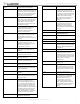
Figure 3: Module Plastic Corner Tabs
4) Insert the module by angling the end of the module where the antennas
are attached downwards, making sure that the edge of the module sits
below the plastic tabs (see Fig. 3). Once the module is seated evenly,
carefully push the bottom of the module into the 8-pin connector beneath
it.
5) Thread the primary antenna’s wire through the channel in the bottom of
the panel. This antenna can then be inserted into the wall behind the
panel. The antenna should be placed at least 3 feet away from the panel,
and in order to obtain optimal reception the antenna should be affixed as
high up as possible.
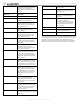
6) The secondary antenna (pre-attached to the module) should be routed
and placed as shown in Fig. 4.
Figure 4: LTE Antenna Routing and Placement
Power Up
Reconnect panel battery and AC power. When an LTE/IP Module is
connected to a powered control panel, the LEDs at the bottom of the module
will become active. It may take a few moments after power up for the LEDs
to become active. If the LEDs do not light up at all, ensure that the module
has been fully inserted into the connector beneath it then perform a full
power cycle by following these steps:
1) Disconnect the battery leads and unplug the panel power transformer
from AC power.
2) Verify that the module is inserted securely and that the antenna is
snapped-in completely.
3) Connect battery leads to the battery. On the XT, make sure to observe
polarity (red to + and black to –) and to keep the wires outside of the tab
holding them in place.
4) Plug the panel power transformer into the AC outlet.
It is important to plug the battery in before plugging in the transformer,
otherwise the panel will issue a “System Low Battery” message regardless of
the battery voltage level.
LTE Phone Test (Module Registration)
To initiate module communication with Alarm.com and the LTE network the
first time, perform a “LTE phone test”.
To perform a Phone Test on a Simon XT:
1) Scroll Down through the control panel menu until it displays “System
Tests” and Press “OK”.
2) Enter the installer code (default 4-3-2-1), then “OK”.
3) Scroll down until the panel displays “Comm Test” and “OK”. The panel will
display “LTE Comm Test in progress” to indicate the test has been
initiated.
Quick Phone Test:
1) On the main screen with the panel disarmed, hold down the ‘3’ key for 5
seconds.
2) The panel will display “LTE Comm Test in progress” to indicate the test has
been imitated.
To perform a Phone Test on a Simon XTi and XTi-5:
1) Press the Status & Settings icon on the lower right of the home screen.
2) Scroll Down and press “Programming”.
3) Enter the installer code (default 4-3-2-1), then “OK”.
4) Press “System Tests”.
5) Press “Comm Test”. The panel will display “LTE Comm Test in progress” to
indicate the test has been initiated.
The Simon XT, XTi, and XTi-5 panel will let you know when the LTE Phone
Test has completed by displaying “LTE Test signal sent OK” on the panel
screen. This indicates that Alarm.com has received and acknowledged the
signal. This does not guarantee that the signal went through to a central
station; it confirms that the Alarm.com Operations Center received the
signal. The central station should be contacted directly to verify that the
signal was received on the correct account and that the Central Station
routing settings have been set up correctly. The signal may not go through
to the central station if (a) the Central Station Account settings were entered
incorrectly on the Alarm.com Dealer Site or (b) if Alarm.com was unable to
send the signal successfully to the Central Station receivers. In these cases
the panel will show a “Fail to Communicate” message.
Required Settings for LTE/IP module
Some panel settings are changed automatically when the LTE/IP module is
connected to the control panel. These settings should not be altered. They
are:
Sensor/Zone 40: Upon initial module power up, the panel recognizes and
learns the LTE/IP module as sensor/zone 40 and assigns “LTE Module” as the
sensor/zone name. Any device previously residing in panel memory as
sensor/zone 40 is automatically deleted and must be learned into panel
memory using any available sensor/zone number between 01 and 39.
Clock: The LTE/IP module sets the panel clock when it connects to Alarm.com
and then updates it every 18 hours. It is important to select the correct panel
time zone on the Alarm.com website, or the panel time will not be accurate.
If a system is powered up before the customer account has been created,
the time zone will default to Eastern Time.
Top of Panel
Plastic
Corner Tabs