
User's Manual


Copyright © 2016 Alarm.com | www.alarm.com | v1.0
3
Simon XT/XTi/XTi-5 LTE/IP Module | Installation Guide
Smoke Supervision: The Smoke Supervision setting (enables 200s smoke
alarm supervision between panel and smoke detectors) for XT version 1.6
and up, XTi version 1.7 and up, and XTi-5 is not compatible with the
Alarm.com LTE/IP module. This setting will be automatically disabled when
the module connects and should not be enabled at the panel. The default
supervision with the Smoke Supervision setting disabled is 1 hour.
Troubleshooting: Module Status Information
Module status information for verifying and troubleshooting module
connection status or errors can be found through the Interactive Services
menus on the XT, XTi, and XTi-5 panels. On Simon XT 1.3 & up, go to the
‘System Test’ → ‘Interactive Services’ → ‘LTE Module Status’ menu. On the
XTi and XTi-5, this information can be accessed through ‘Programming’ →
‘Interactive Services’ → ‘Module Status’.
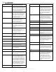
See Table 1 below for potential module statues.
Table 1: LTE/IP module satuses
Idle
Most common state
Roaming
Roaming on partner network.
PowerSave Mode
AC Power is Down
Registering…
Same as 3 flashes on LED L1
Connection Error
Same as 4 Flashes on LED L1
Radio Error
Radio is not operating correctly, same as 5
flashes on LED L1
Server Error
Same as 8 flashes on LED L1
Connected
Currently talking to Alarm.com Servers
Connecting…
In the process of connecting to Alarm.com
Updating…
Updating Signal Level
In addition, some of the information can be retrieved on the Simon XT via
long key presses from the keypad. Press and hold the following panel keys
for 10 seconds to display the given information on the panel display. Most
messages are displayed for less than 30 seconds but can be cut short by
pressing the # Key for 10 seconds.
Table 2: LTE/IP module Statuses
1 Key
10-digit module serial number. This number is needed to create
the Alarm.com customer account.
2 Key
Module firmware version. (e.g. 4183a)
3 Key
Performs Phone Test
5 Key
Wireless signal strength level and module status or error, if any.
The panel will display bars for the signal level (0 to 5) and a
number (2 to 31) followed by the Mode it is in. (See “LTE/IP
module statuses” on Table 1).
6 Key
Battery voltage as read by the module, to two decimal places, and
the AC power status. (e.g. Battery: 6.79v, AC Power OK)
8 Key
LTE frequency used by the module: "High" = 1700MHz; "Low"
= 700 MHz.
Various Module States (Modes)
There are three module states, or modes, as described below:
Idle Mode. AC power is OK and the module is not currently talking to
Alarm.com.
PowerSave Mode. The module just powered up, AC power is down, or AC
power was recently restored and the battery is recharging. The module is
fully functional and will go into Connected Mode as soon as a signal needs to
be sent. Press and hold the 5 Key for 10 seconds to switch the module into
Idle Mode and update the signal level reading. The system will go into Idle
Mode every 2 hours to check for any incoming messages.
Connected Mode. The module is currently talking to Alarm.com. The
module stays in Connected Mode for at least four minutes after reporting
an event to Alarm.com, unless the 5 Key is pressed and held for 10 seconds,
which will cause the module to go back to Idle Mode.
Sleep Mode. The panel is not connected to AC power, or there is an AC
power failure, and the battery level is low. The module will connect to
Alarm.com to send a signal, but will otherwise draw almost no power.
Note: If the LTE/IP module is powered down for a short period of time,
buffered messages from Alarm.com may be received when module power is
restored.
Improving Wireless Signal Strength
Guidelines for optimal wireless signal strength:
•
Install the module above ground level, as high up as possible within the
structure.
•
Install the module near or adjacent to an outside-facing wall of the
structure.
•
Do not install the module inside a metal structure or close to large
metal objects or ducts.
•
Make sure to follow the antenna positioning guidelines that are
included with the antenna. Certain antennas must be oriented a specific
way in order to receive signals.
•
Upgrade the antenna. If using the 1/4 wave antenna included with the
LTE/IP module, upgrade to a remote cable antenna. Contact Alarm.com
technical support for antenna options.
As you make changes to the module location or antenna to improve signal
strength, request updated signal readings to verify changes. To request an
updated reading, press and hold the “5” key for 10 seconds on the XT or
press the ‘Refresh’ button in the “Module Status” menu on the XTi or XTi-5.
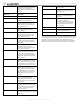
Table 3: Simon XT 1.3 and up Interactive Services Menu
Menu
Description
System Programming +
Installer Code
Scroll down to System Programming,
enter the Installer Code and press OK
- Interactive Services
Scroll up to Interactive Services and press
OK
-- LTE Module Status
Scroll down through the various LTE
module information screens
--- Radio
Signal level, connection status, roaming
status, and errors (if any)
--- LTE Freq.
LTE frequency used by the module.
--- LTE Band
By default the module will choose the best
LTE band.
--- Battery
Current battery voltage and AC power
status
--- SN
Module serial number. Needed to create
or troubleshoot an Alarm.com account.
--- SIM card
IMSI number. Sometimes needed to
troubleshoot an account
--- Version
LTE module firmware version and sub-
version. Example: 4183a, where 4 = XT,
183 = module firmware version, a =
subversion (the label on the module will
say X183)
-- Z-Wave Setup
2
This menu is used to add, remove, and
troubleshoot Z-Wave devices and
networks. To control Z-Wave devices via
the Alarm.com website and smart phone
apps, you will also need to enable Z-Wave
services on the account.