
User's Manual

Interlogix part number: 600-9400-IMAG
Alarm.com part number: ADC-IS-200-LP
Alarm.com Image Sensor Installation Guide
1 Copyright © 2012 Alarm.com. All rights reserved. Rev 3.2
PRODUCT SUMMARY
The Image Sensor is a pet immune PIR (passive infrared) motion detector with a built-in
camera. The sensor is designed to capture images during alarm or non-alarm events
when motion is detected. Users can also initiate image capture on-demand to
Peek-In on their property. Images are stored locally and uploaded either automatically
when motion is captured during alarm events or manually when requested by the user.
Once uploaded, images are available for viewing on the Alarm.com Website or an
Alarm.com Smart phone app. The sensor is battery powered, all wireless and simple to
install and operate. Both an Alarm.com module and a subscription to an Alarm.com
service plan are required.
Highlighted Features
• Battery operated
• Communicates wirelessly to the security control panel
• 35 feet by 40 feet detection coverage area
• Configurable PIR sensitivity and pet immunity settings
• Image: QVGA 320x240 pixels
• Color Images (except in night vision)
• Night vision image capture with infrared flash (black & white)
• Tamper detection, walk test mode, supervision
Service Plan Options
Image capture features require either an Alarm.com Basic or Advanced Interactive Service
Plan and one of the following Image Sensor add-ons:
• Image Sensor Alarms- Includes upload of images from alarm events only.
• Image Sensor Plus- Includes upload of images from alarm events and non-alarm
events. Users can configure Daily View schedules to receive images automatically each
day or Peek-In to initiate an on-demand image capture immediately, or when the next
motion occurs. Users can also request images that are captured automatically while the
system is Armed Away or following a Disarm from an Armed Away state. Up to 40
captured events can be uploaded per month. Additional image uploads may be added
in increments of 20 at an additional charge.
Choose Sensor Location and Mount
a. Determine sensor mounting location based on installation scenario and criteria
noted in the “Installation Guidelines.” For best image capture, the target capture
areas should be centered in the frame. (e.g. If customer wants to capture people
coming through door, the doorway should be centered in camera/PIR view.)
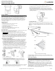
b. Determine desired mounting angle for customer scenario; attach mounting arm to
sensor-back and re-attach sensor to sensor-back. The mounting arm attaches to the
back of the sensor enabling the sensor angle to vary based on the application. To
obtain the full 35’ x 40’ coverage area, the sensor should be mount the sensor at a
6˚ downward angle. This corresponds to a “teeth up” orientation of the mounting
arm. For most smaller areas in residential installations, mount the arm with the
“teeth down” for a deeper angle (18˚). Secure the back of the sensor to the mounting
arm with the provided screw. If the camera will be mounted
perpendicular to the wall, mount the sensor without the mounting arm/bracket di-
rectly on the wall, at a 12° angle.
Mounting Arm Orientation Attach Mounting Arm to Sensor-Back Attach Sensor to
(Top: Teeth Up, Bottom: Teeth Down) Sensor-Back
c. Choose applicable mounting bracket for customer scenario. The sensor
hardware packet contains 2 mounting brackets for different mounting scenarios.
Use the provided large screws and anchors to attach the bracket to the wall.
Flat Wall Mount Corner Wall Mount
Mark location of bracket holes on mounting surface at a height of 8 feet for maximum
coverage area. (Leave at least 3 inches of clearance above the sensor to allow for
battery replacement without uninstalling the mounting bracket.)
d. Place sensor with arm on mounting bracket. Adjust the horizontal positioning of
the sensor to point towards the desired coverage area. To adjust positioning, lift the
mounting arm at least 1/3 of the way off the bracket and rotate the arm.
e. Secure the mounting arm location by sliding lock pin into the hole. Use the
washer and remaining small screw to secure the lock pin by screwing upwards
through the bottom of the hole in the mounting bracket. (Note: To make it easier to
adjust PIR/camera field of view in step 10, complete this step after horizontal sensor
positioning is finalized.)
9. Complete PIR Testing & Verify RF Coverage
Verify that PIR coverage adequately covers area by performing a walk test. (See “Pro-
gramming” section for more details.) Verify that the sensor signal strength is strong
while mounted. The signal strength must be above 30% for the sensor to function
properly.
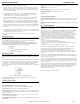
PIR Lens and Camera Coverage Diagrams
Figure 1.Side View: PIR Lens Coverage
Figure 2.Top View: PIR Lens Coverage
As indicated in Figure 2, the camera coverage area is narrower than the PIR coverage
area. When installing, mount sensor where subjects are likely to be centered in or across
PIR and camera field of view.
INSTALLATION GUIDELINES
Before permanently mounting the Image Sensor, evaluate potential locations and consider
the following factors to ensure optimal performance and false alarm protection:
Range- Is the location close enough to the security panel to ensure adequate signal
strength?
False Alarm Immunity- Is installation location false alarm prone? Reduce the risk of
motion-triggered false alarms by making sure the location is free of vibration and the
device does not face a local heat source, window, or areas with high pet activity. (Also,
make sure area is free of elevated surfaces where pets may climb.)
Capture Orientation- Is the location ideally suited for detecting motion and capturing
images when there is an intruder or activity? Consider where the subject is likely to enter
the area and whether or not they will be facing the sensor.
40 ft
20 ft
20 ft
0 ft
40 ft
50
°
90
°
8 ft.
(2.4m)
5.9
ft.
(1.6 m)
16.5
ft.
(4.7 m)
40
ft.
(12 m)
Camera
Angle
Washer & Screw
Back Pin
Screw
s