
User's Manual

Alarm.com Image Sensor Installation Guide
2 Copyright © 2012 Alarm.com. All rights reserved. Rev 3.2
Lighting Conditions- How good is the artificial and natural light? Will daytime and
nighttime lighting conditions ensure adequate image quality?
• If possible, locate sensor within 100 ft of the panel especially if there are many walls
between the sensor & panel, or if the panel and sensor are located on different floors.
While the transmitter may have an open air range of 400 ft, installation site conditions
can reduce range considerably.
• Avoid facing the sensor toward or close to areas that may affect communication such
as metallic objects or electronics likely to produce interference. Verify sensor RF
communication at panel, even if within recommended distance.
• For optimal detection capabilities, mount the sensor where someone will most likely
walk across the sensor coverage area as opposed to directly towards the sensor.
• By default, the Image Sensor is set to “Normal” sensitivity. A more sensitive motion
profile (“High”) and a less sensitive profile providing pet immunity for pets up to 40 lbs
(“Low”) can be selected at the control panel or through the Alarm.com Dealer Website.
• The Image Sensor is designed for indoor use only and should not be installed outdoors.
For proper operation in pet immune applications, the room should be kept between 60°
and 110° F.
• To maximize night vision image quality, do not orient sensor towards surfaces that will
create glare when infrared flash occurs. Avoid orienting the sensor such that the ceiling
or adjacent walls are in the camera field of view.
• The sensor must be mounted on a flat wall surface (do not set on shelf) free of
vibrations.
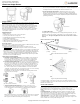
SENSOR RESET BUTTON
Insert a paperclip into the hole on the front of the sensor to access the reset button. Press
and hold for 3 seconds to power cycle the sensor. Press and hold a full 10 seconds until
the sensor LED flashes rapidly to reset the sensor and clear it from its network. The
sensor must be reset prior to enrolling in a new network.
(Note: The sensor can only be cleared from its network using the reset button if it is
currently not communicating with its network. If the sensor is still communicating with its
network, clear sensor by deleting it from the system it is enrolled in.)
Figure 3.Sensor Reset Button
BATTERY REPLACEMENT
When a sensor‘s batteries are low, the panel will display a low battery alert for the sensor
(unless this trouble condition has been disabled for the panel display). Notifications are
also issued via the Alarm.com platform if the customer has subscribed to this notification
type.
(Note: Low battery messages are only active at the panel between 7:00am and 10:00pm.)
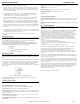
To replace the sensor batteries, slide the front of the sensor up off the sensor-back. (No
need to remove or un-mount entire sensor-back and mounting arm.) To maximize battery
life, replace the sensor batteries with 2 AA 1.5v Energizer Ultimate Lithium batteries.
Dispose of used batteries according to the battery manufacturer instructions and following
local regulations.
Figure 4. Removing Sensor for Battery Replacement
(Note: The operation of the sensor with alkaline batteries has not been verified for
compliance with UL standards.)
TECHNICAL SPECIFICATIONS
Alarm.com Model Number: ADC-IS-200-LP
Interlogix Part Numbers: Image Sensor: 600-9400-IMAG
Image Sensor Kit (Image Sensor w/ daughterboard): 600-9400-IMAG-KIT
Power Source: 2 AA 1.5v Energizer Ultimate Lithium Batteries
Expected Battery Life: Approximately 2 years. Battery life varies by use case depending
on certain factors such as weak signal strength and frequency of motion activations, image
captures, and IR flashes.
Voltage Thresholds: Low battery alerts are issued at 3.05V. The sensor cannot operate
when the voltage reads below 1.95V.
Operating Temperature Range: 32° to 110°F for non-pet applications, 60° to 110°F for
pet applications
Weight: 3.1 oz. (with batteries, without mounting accessories)
Dimensions: 3.1’’ h x 1.8’’ w x 2.3’’ d
Supervisory Interval: 100 minutes (sensor), 3 hours (alarm hardwire)
Wireless Signal Range: Greater than 400 ft open air
Color: White
Recommended Mounting Height: 8 ft
Recommended Mounting Angle: 6° for large coverage area and rooms greater than 30
ft (“teeth up” on mounting arm); 18° for rooms less than 30 ft (“teeth down” on mounting
arm)
Motion Profiles & Sensor Range: Normal (up to 30 ft, default), High (up to 35 ft), Low (up
to 25 ft)
REGULATORY INFORMATION
Changes or modifications not expressly approved by Alarm.com can void the user’s
authority to operate the equipment.
This equipment has been tested and found to comply with the limits for a Class B digital
device, pursuant to part 15 of the FCC Rules. These limits are designed to provide
reasonable protection against harmful interference in a residential installation. This
equipment generates, uses, and can radiate radio frequency energy and, if not installed
and used in accordance with the instructions, may cause harmful interference to radio
communications. However, there is no guarantee that interference will not occur in a
particular installation. If this equipment does cause harmful interference to radio or
television reception, which can be determined by turning the equipment off and on, the
user is encouraged to try to correct the interference by one or more of the following
measures:
• Re-orient or relocate the receiving antenna.
• Increase the separation between the equipment and receiver.
• Connect the equipment to an outlet on a circuit different from that which the receiver is
connected
• Consult the dealer or an experienced radio/TV technician for help.
This equipment complies with the FCC RF radiation exposure limits set forth for an
uncontrolled environment. This equipment should be installed and operated with a
minimum distance of 20 centimeters between the radiator and your body.
Under Industry Canada regulations, this radio transmitter may only operate using an
antenna of a type and maximum (or lesser) gain approved for the transmitter by Industry
Canada.
Conformément à la réglementation d'Industrie Canada, le présent émetteur radio peut
fonctionner avec une antenne d'un type et d'un gain maximal (ou inférieur) approuvé pour
l'émetteur par Industrie Canada.
This device complies with Industry Canada licence-exempt RSS standard(s). Operation is
subject to the following two conditions: (1) this device may not cause interference, and (2)
this device must accept any interference, including interference that may cause undesired
operation of the device.
Le présent appareil est conforme aux CNR d'Industrie Canada applicables aux appareils
radio exempts de licence. L'exploitation est autorisée aux deux conditions suivantes : (1)
l'appareil ne doit pas produire de brouillage, et (2) l'utilisateur de l'appareil doit accepter
tout brouillage radioélectrique subi, même si le brouillage est susceptible d'en
compromettre le fonctionnement.
FCC ID: YL6-143IS20 IC: 9111A-143IS20
Hold Here
Slide Up
Insert Paperclip to access reset button