
Installation Manual


MAGNETIC LOCK WIRING INSTRUCTIONS
MODELS WITH BOND SENSOR AND DOOR STATUS SENSOR
600LB, 600DLB, 1200LB, 1200D
To remove the header plate, it may be necessary to remove the wiring compartment screw. A long wiring
compartment screw can be used to increase security by limiting access to the header plate mounting
screw from below the lock.
LED AND BOND SENSOR STATUS
ASSA ABLOY, the global leader
in door opening solutions
Alarm Controls Corporation
Deer Park, New York 11729
(800) 645-5538
www.alarmcontrols.com
LBInst7-13
LED BOND SENSOR RELAY* DOOR MAGLOCK
OFF OFF OPEN OR CLOSED NOT POWERED
GREEN ON CLOSED** POWERED
RED OFF OPEN POWERED
*The bond sensor detects the holding force of the maglock and the Bond Sensor Relay will remain off until the sensor detects over
90% of the rated holding force.
**Closed and locked. Maglock and armature plate properly installed and operational.
DOOR STATUS SENSOR SWITCH STATUS
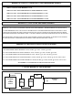
A terminal block is provided for wiring the maglock to the power supply and for the Bond Sensor Relay outputs.
A pair of flying leads are provided for the Door Status Sensor (Reed Switch). These are the Green and White wires.
It may be necessary to lift up the board to get to the Green and White wires.
ALIGNMENT OF THE MAGLOCK AND ARMATURE PLATE
DOOR WHITE AND GREEN FLYING LEADS
OPEN OPEN
CLOSED CLOSED
WIRING INSTRUCTIONS
VOLTAGE IS FACTORY SET FOR 24VDC OPERATION. For 12VDC operation, access the voltage
selection switch via the wiring compartment.
600 Series 1200 Series
Align the maglock and armature plate as shown.
Armature plate must be mounted to door using the
rubber washer sandwiched between the metal washers
provided. Do not excessively tighten bolt. Armature
must float on door. Screw locking agent is provided on
each screw.
PERMANENT MAGNET
DOOR STATUS SENSOR
ANTI-ROTATION PINS
WIRING
COMPART-
MENT
ARMATURE PLATE
MAGLOCK
MECHANICAL KICK-OFF DEVICE
UNIVERSAL MOUNTING BOLT HOLE
FOR STANDARD OR OFFSET
MOUNTING OF ARMATURE PLATE