
Installation Instructions

Page 2
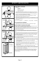
1. Prepare door jamb per appropriate template detail.
2. Install mounting tabs using #10-32 screws. Do not
tighten. Set tabs for 1/8” thick face plate.
3. Connect wires coming from the low voltage power
source (see wiring diagrams and electrical specifications
on page 3).
4. NOTE: It is important to allow enough space behind the
electric strike in the jamb cut-out for the wires.
Bunching the wires inside the electric strike body may
cause the unit to not operate properly.
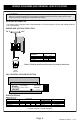
5. Install electric strike and option face plate to jamb
using #12–24 machine screws or wood screws provided
in the option package.
6. Secure #10-32 screws holding mounting tabs (when
applicable).
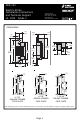
Cutout dimensions for 7-15/16“ Faceplate.
R5/32"
[3.97]
3-3/8"
[85.73]
7/8"
[22.23]
7-15/16"
[201.61]
7-7/16"
[188.98]
1-3/8"
[34.93]
2-1/4
[57.15]
1-1/8
[28.57]
1-1/4
[31.8]
1-3/4
[44.45]
3/4
[19.05]
3-3/8
[85.73]
4-7/8
[123.83]
3-1/2
[88.9]
3/8
[9.53]
4-1/8
[104.77]
12-24 TAP
STRIKE
LOCK
VERTICAL
CENTERLINE
5/8
[15.88]
1-1/4
[31.8]
CYLINDRICAL
LOCKSET
STRIKE
PLATE
Cutout dimensions for 4-7/8“ Faceplate.
Note: 1020 has radius corners.
3-3/8"
[85.73]
7/8"
[22.23]
4-1/8"
[104.77]
4-7/8"
[123.83]
3-1/2"
[88.89]
#12-24 Thread
1-1/4"
[31.75]
R5/32"
for 4-7/8“ RD.Faceplate
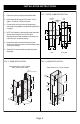
Door Jamb
Door
FIG. 1: DOOR JAMB DESCRIPTION
FIG. 3: JAMB INSTALLATIONFIG. 2: JAMB INSTALLATION
INSTALLATION INSTRUCTIONS