
Installation Instructions

Page 3
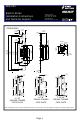
Door
"A"
Deadlatch
Face of Latchbolt
OPENING
DIRECTION
Door
Face
"B"
Rebate
Silencer Buttons
or Weatherstripping
Stop
Door Jamb
"C"
Vertical Centerline
of Mounting Screws
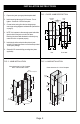
TO FIND VERTICAL CENTERLINE
When Jamb:
• is not squared
• is warped
• has heavy weather stripping
• conditions are not ideal
1. To determine the location of the Vertical Centerline of the mounting screw holes, first measure
the distance from the outside face of the door to the face of the latchbolt (distance “A”) (see F
IG. 7).
2. Close the door and measure the distance from the outside face of the door jamb (distance “B”)
(see F
IG. 8). Do not force the door against the stop, close gently .
3. If the jamb face extends beyond the face of the door, add A and B (see F
IG. 8). If the door
extends beyond the jamb face, subtract B from A (see F
IG. 9).
4. Using the dimension obtained add 9/32” [7.14 mm] (see F
IG. 10). The resulting dimension “C” is the
distance from the jamb face along the rebate to the mounting hole centerline of the Alarm Controls
AES-100 Series Electric Strike.
TO FIND HORI ZONTAL CENTERLINE
1. Mark the location of the lock centerline on the jamb face, as shown in figure 1 on page 1 .
FIG 7
F
IG 10
F
IG 8
Door
Face
"B"
Rebate
Silencer Buttons
or Weatherstripping
Stop
Door Jamb
FIG 9
Jamb face extends
beyond face of the door .
Dimension A + B
Door face extends
beyond face of the jamb.
Dimension A - B
D
IMENSION C =
A + B + 9/3 2” [7.14]
OR
A - B + 9/3 2” [7.14]
Vertical Centerline:
Dimension A ± Dimension B + 9 /32” [7.14 mm] = Dimension C
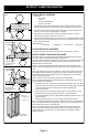
ELECTRIC STRIKE TROUBLE- SHOOTING GUIDE
If the electric strike does not operate properly after installation, the following problems may need to
be corrected. Please read carefully before calling for technical service.
Step 1. If the electric strike does not oper
ate properly, open the door and re-energize the electric strike.
If the electric strike operates properly with the door held open, the lockset may be pre-loading or
binding the keeper of the electric strike.
Solution: The horizontal relationship bet ween the lockset and the electric strike will have to be
adjusted to eliminate the binding between the bolt of the lock and the electric strike keeper (also see
note 2.)
Step 2. If the electric strike does not oper ate with the door open, remove the electric strike from the
jamb leaving the wiring connected and re-energize the electric strike. If the electric strike operates
properly outside of the jamb, then the problem may be from a tight-fitting jamb cutout pinching the
sides of the electric strike together.
Solution: The electric strike cutout in the door jamb needs to be slightly enlarged.
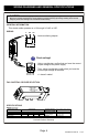
Step 3. If all mechanical problems have been eliminated without successful electric strike operation
check the following electrical problems:
a. Examine the power supply or transformer to verify that the output voltage is at the listed rating
b. Verify that the po wer wires leading to the electric strike are a large enough gauge to handle the
current requirements. Note: Some voltage may be lost when using smaller gauge
wires over long distances.
c. Using a multimeter: Verify that the input voltage is within the recommended limits (+/- 10%)
d. Confirm that the input voltage at the installation site is DC or properly rectified AC.
e. Verify that all peripheral devices such as bridge rectifiers, SMART-Pacs, buzzers, LEDs etc. are
properly connected.
f. Check that the switch, key pad, etc., meets the voltage requirements for the system.
Note 1: A quick way to determine if an electric strike is defective is to install it in a site where another
electric strike has been installed and working properly . Another way is to use an alternative power
source to test the electric strike (i.e. a DC battery pack.)
Note 2: If the voltage is slightly too lo w to operate the electric strike, a 35 volt, 220 micro farad
capacitor may be installed across the bridge rectifier (positive to positive, negative to negative) to
provide an initial boost of power to the unit. This is also helpful to overcome slight pre-loading
conditions (as in step 1.)
RETROFIT JAMB PREPARATION