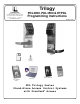
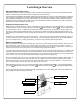
Trilogy 345 Bayview Avenue Amityville, New York 11701 For Sales and Repairs 1-800-ALA-LOCK For Technical Service 1-800-645-9440 Publicly traded on NASDAQ Symbol: NSSC PDL3000, PDL3500 & ETPDL Programming Instructions © ALARM LOCK 2006 WI1021C 9/06 PDL3000 PDL3500 ETPDL HID HID CORPORATION PROXCARD® AL-DTM DATA TRANSFER MODULE PROXKEY® KEYFOB DL-WINDOWS PROGRAMMING SOFTWARE AL-PRE PROXCARD® READER / ENROLLER AL-IR1 PRINTER PDL Trilogy Series Stand-Alone Access Control Systems with ProxCard® A
PDL SERIES LOCKS THE ALARM LOCK TRILOGY PDL-SERIES STAND-ALONE ACCESS CONTROL SYSTEM IS A SERIES OF STATE-OFTHE-ART MICROPROCESSOR-BASED PROGRAMMABLE KEYPAD-ENTRY AND PROXIMITY SECURITY LOCKS. PDL3000, PDL3500 & ETPDL PDL3000 Features an HID compatible ProxCard® reader, and a real-time clock/calendar that automatically adjusts for Daylight Saving Time and allows for automated programming of events.
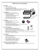
PDL Series Lock Features Audit Trail • • • • • • 40,000 Event Capacity Entries Logged with Time and Date Critical Programming Events Logged Printable using the AL-IR1 Hand-Held Printer (see page 23, Function 55) Uploadable using Alarm Lock's DL-Windows software (see page 23, Function 58) Transferable to AL-DTMs (see page 24, Function 59) Two-Color Status LED Lock Features • • • • • • • Metal Key Override for all cylindrical locks Keypad Lockout (see page 24, Functions 60-61) Non-Volatile (Fixed) Memory
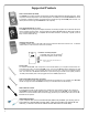
Supported Products Data Transfer Module (AL-DTM) An AL-DTM can be used to transfer Lock Programs (and other data) between DL-Windows and locks. When computers cannot be transported or when electrical power is not available, the hand-held AL-DTM device acts as a go-between--it allows the transfer of lock data from the computer (through the AL-DTM) and to the lock, or in reverse (from the lock through the AL-DTM back to the computer).
Lock Design Overview Why Use Software inside a Lock? With ordinary door locks, the need to make physical copies of metal keys and distributing them can be a huge organizational and financial task -- and what will you do if someone causes a security breach by losing their key? The answer lies in the advantage of SOFTWARE. Software (also called "firmware") is not "hard" or "fixed" like hardware is. Software is "soft" -- flexible and changeable to your needs.
Terminology Used in this Manual What is a Lock Program? What is a Programming Level? A Lock Program contains the instructions that a lock uses to perform its various functions. You can use the keypad to create a Lock Program stored within the lock. You can also use DLWindows (defined below) to create a Lock Program on your computer, and then transfer and store the Program in the circuitry contained inside the lock itself.
Terminology Used in this Manual (cont'd) 2000 Users in its programming memory. This memory can be thought of as simply a numbered list from 1 through 2000. Each entry in the list is represented by a User Number. Therefore, where a User is located in this list--their User Location--is a commonly used description of their User Number. Because of their similarities, a User Number, User Location and Location Number can be used interchangeably. In some DL-Windows screens, the word "Slot" is also used.
Programming Levels The Programming Level defines the range of programming tasks a User is allowed to perform. The higher the Level, the more programming tasks the User is allowed (with Master allowing ALL tasks). Note: Since the Programming Level is closely associated with the type of User and their abilities, a User who holds a certain Programming Level is sometimes referred to by their “User Type”.
Conventions Used in this Manual 2 Enabling/Disabling Users (By User Number) Minimum Required Program Level User Number must be between 2 and 2000. NOTE: Will Enable/Disable users even if the user is associated with an enabled group. Function Description Program Levels are abbreviated as follows: 3. Disable User ;3 ;[___]: 4.
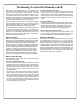
Product Communication Examples Send to lock Receive from lock If your computer does not have a serial COM port (DB-9 male) available, you can plug your AL-PCI2 cable into a special USB to RS-232 cable. Order part PCI-USB for the USB to RS-232 cable only, or ALPCI2-U for both the USB to RS-232 cable and an AL-PCI2 cable).
Wiring and Power Up WIRING See the Installation Manual for more information. Batteries: Use only 1.5 volt Duracell Alkaline size-AA batteries. External Power: Red / Black wires - External 7.5 VDC Power Source must be used for operation without batteries. Remote Input: White / White wires - Wire a Normally Open Contact to wires (white and white). Momentarily close to allow person to pass through door. NOTE: Remote Input is enabled from the factory.
Quick Start First Time Start Up 1. Unpack the lock. 2. With the batteries disconnected, hold down the ; key for 10 seconds and release. 3. Connect the batteries and listen for 3 beeps. Within 5 seconds of hearing the 3 beeps, press and hold ; until beeping starts. This will clear the lock of all programmed data. Important: If you do not hear these 3 beeps, you must start over at step 2. 4. Listen for another series of beeps and LED flashes followed by 10 seconds of silence. The lock is now ready to program.
Quick Start (cont’d) Delete a User Code 1. Enter Program Mode (if not in already). 2. Press ; 2 ; [User Number] :. The lock will flash a green LED and beep continuously for 6 seconds. When the red LED flashes, the User Code is deleted. 3. Repeat step 2 for each new User. User Code Conflicts Care should be taken not to program a new User Code which matches the first digits of any other User Code (only the User Code with the least number of digits will be recognized).
Exit Program Mode Hold Down any key for 3 seconds. Program Mode exit is confirmed by several beeps. You are now in normal operation. Re-enter Program Mode If you wish to re-enter Program Mode, key-in your new 6-digit Master Code, and press ;. You are now ready to mount and install your PDL series lock and give out your User Codes. Before installation, it is suggested you test and verify that all User Codes entered are active (see below).
Programming Functions--Overview Function 1 Change Master Code See page 16 Function 48 Enable Passage Mode See page 22 Function 2 Add/Delete/Change User Codes See page 16 Function 49 Disable Passage Mode See page 22 Function 3 User Disable (By User Number) See page 17 Function 50 Return Lock to Normal Passage Mode Schedule See page 22 Function 4 User Enable (By User Number) See page 17 Function 51 Passage Mode Configuration See page 22 Function 5 User Enable with Timeout See page 17
Programming Functions USERS ;1 1. New Master Code (User Number 1) ;[______] ;[______]: (New Master Code) • Master Code must be 6 digits-only. • Master Code is Keypad Code Access only. • Factory Default = 123456 (Confirm New Master Code) M • See "Lock Design Overview" on page 5 for more information about Master Codes. 2. Add/Delete/Change User Codes 2-2000 ;2 ;[____] * ;[______]: (User Number) • User Number must be between 2 and 2000.
Programming Functions (cont'd) USERS (Continued) User Enable/Disable (By User Number) • User Number must be between 2 and 2000. 2 NOTE: Will Enable/Disable Users even if the User is associated with an enabled Group. Use Feature 3 to disable a specific User Number and their associated User Code. If the disabled User Code is entered, the lock will flash 1 Green and 4 Red Flashes (with 1 long and 5 short beeps) indicating that the User Code exists in memory, but is disabled.
Programming Functions (cont'd) CLEAR FUNCTIONS 12. Clear All Schedules and Timeout Functions ;12 ;000: Function 12 clears all programmed Schedules and all Timeout Functions. (To clear All Timeout Functions only, see Function 13 below). Function 12 will clear all of the following: All Schedule Functions 72 through 93, Timeout Functions 5, 25 through 34 and Function 47. Note: Function 12 also resets Passage Mode and any disabled Groups.
Programming Functions (cont'd) NOTE: GROUPS Clear All Timeout Functions by entering Function 13. Group Enable/Disable with Timeout (Enter Timeout, XXX Hours) (Functions 25-34 are enabled through the keypad only) • Hours must be between 1-999. Enter the functions below to Enable/Disable Groups for the amount of time entered in hours. 2 NOTE: Only 4 Timeout Functions are allowed at any one time. An error beep will sound when attempting to program more than 4 Timeout Functions.
Programming Functions (cont'd) CLOCK SETTINGS 38. Set Date ;38 ;[ ______]: (Date) • Use Month Day Year format - MMDDYY - Single digit months and days are entered with a preceding zero. • Enter ONLY the last two digits of the year. For Example: March 8, 2002; Enter: ;38 ;03 08 3 02: 39.
Programming Functions (cont'd) CLOCK ADJUST Clock Adjust Number of seconds to adjust (speed up/slow down) the clock each day must be between 0-55 seconds. Note: Repeated use of these Functions are not "cumulative" (this means, for example, if the clock has already been set to speed up 10 seconds per day, and then is found to need an additional 10 seconds, then program 20 seconds using Function 43). 4 Clock Accuracy The internal oscillator is factory calibrated to an accuracy of ±5 minutes/year.
Programming Functions (cont'd) PERMANENT PASSAGE MODE Passage Mode Enable/Disable - Schedule will not Override • Function 48 allows passage through the door without the need for a User Code. Re-Lock using Function 49. • Programmed Schedules will not override the state of the lock using functions 48 and 49. If it is required that programmed 2 schedules override Passage Mode, Enable/Disable Passage Mode using Functions 45/46.
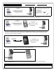
Programming Functions (cont'd) PRINTER Hold the printer perpendicular to the Lock’s infrared LED as shown in Figure 1 and Figure 2. If the printer has been idle for some time, press the paper feed button to wake up the printer. Infrared LED Infrared LED Infrared Reader PDL3000 to Printer - Side View Place Infrared Reader (on printer) in front of the Infrared LED (on lock) Figure 2 Figure 1 55.
Programming Functions (cont'd) 59. Reserved LOCKOUT 60. Number of Attempts Before Lockout ;60 ; [_]: (Number of Attempts) • Number of attempts before lockout must be 1-9 attempts. • The number of attempts is reduced by half every time the keypad is locked out without a successful code entry (default is 6 attempts). • The attempt count is reset each time a valid code is entered. 61. Set the Attempts Lockout Time ;61 4 ; [__]: (Lockout Time) • Lockout Time must be 1-60 seconds.
Programming Functions (cont'd) SYSTEM FEATURES 67. Add System Features ;67 ; [__]: (Event Number) 4 • Relay Features (12-24. Reserved) Use Function 67 to program one or more lock events and the Relay will energize when the programmed event(s) listed below occurs. For example, program ; 6 7 ; 3 : and when an attempted entry fails (such as a User who enters an incorrect or un-programmed User Code), the Relay will energize for 2 seconds.
Programming Functions (cont'd) ENTER KEY Enter Key • When this function is enabled, the User must press : after any valid User Code entry. Therefore, this Function allows User Codes to be subsets of other User Codes. 4 Examples: 1 2 3 : can be a valid user code; 1 2 3 4 : can be a valid user code within the same lock. 1 2 3 4 5 6 : (Hold ;) for Master User Code to enter Program Mode. 69. Enable : as Enter Key ;69: 70. Disable : as Enter Key ;70: 71.
Programming Functions (cont'd) QUICK SCHEDULES Quick Schedules - Enable Group For your convenience, your lock comes pre-programmed with Quick Schedules, which, when programmed, enable Groups for popular blocks of time. Group members will be enabled during the blocks of time defined below, but will still need to enter their User Codes into the keypad to unlock the lock. • Group number must be 1-4; enter the number of the Group that is to be enabled for the time specified by the Quick Schedules below.
Programming Functions (cont'd) SCHEDULES GROUP 1 ACTIVATED Scheduled Relay Activation (Group 1 Activated) Functions 90 and 91 allow you to set up a window of time where if any Group 1 User Code is entered within this window, the relay will be activated for 2 seconds. This relay is for use with a Control Panel that has a key switch disarm option. For additional information, see Group 1 Activated Features on page 30. • Also program Relay Function 6 using Function 67 (; 6 7 3 ; 6 :).
Programming Functions (cont'd) Scheduled Group 4 Enable (Group 1 Activated) Functions 92 and 93 allow you to set up a window of time where if any Group 1 User Code is entered within this window, Group 4 members will be enabled. (Group 4 members will still need to enter their User Codes to enter). For additional information, see Group 1 Activated Features on page 30.
Groups and Scheduled Group 1 Examples The following examples detail the more advanced features of the PDL series locks. Although all features and device functions can be programmed using the lock keypad, when programming becomes more complex you may find it easier to use DL-Windows software to program your Alarm Lock security lock. For more information, contact your Alarm Lock security professional.
Groups and Scheduled Group 1 Examples (cont'd.) Functions 90/91: Use Function 90 and 91 (see page 28) to create a window of time where if any Group 1 User Code is entered within the programmed window, a Relay will be activated for 2 seconds. The Relay can be configured to disarm a burglary control panel. See page 28. 1. Enter Program Mode (if not in already). 2. Connect Relay to a burglar control panel with switch input for disarming. 3.
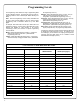
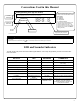
Default Values are shown in parentheses. Function Number(s) 43/44 Function Name Clock Adjust Programming 0-55 +/(0) 52/53/54 Pass Time 60 Set Lockout Attempts (0) Seconds (3 sec) 10 sec 15 sec 1-9 Attempts (6) 61 Set Lockout Time 1-60 seconds (1) 64/65 Remote Input Momentary 66 Ambush Code (Enable) Add Relay/System Features Disable 00-99 (9) 67 (8) (9) Ambush Code Check all that apply 1. Remote Input switch closed and Function 65 Remote Input enabled 2.
User Number (1-2000) User Code (3-6 digits) Group Association 1 2 3 User Name 4 Note: For a complete list of user codes, obtain a printout from either the remote printer (Program Function 56) or using the DL-WINDOWS Software.
Day(s) Function Number Up to 500 scheduled functions can be programmed (Up to only 150 using AL-DTM2).
Glossary ACCESS = Entry into a restricted area. AMBUSH = A special Code entered at the keypad when the User is forced to unlock a device. The device unlocks but sends a silent alarm with no indication at the keypad. Can be used to trip a relay, to alert security, or trip a silent alarm on a Burglary Control Panel. AUDIT TRAIL = A date/time stamped log of previous lock events. BURGLARY CONTROL PANEL = Provides local alarm and remote communication to request security for burglary/break-in.
Glossary (cont'd) PROGRAM MODE = A mode allowing program/data to be entered through the keypad. Only specific Users can program a lock manually, by entering their USER CODE, followed by the [;] SCHEDULES, QUICK = Any one of four most common types of schedules can be programmed. key. To exit program mode, hold any key until repeated beeps are heard. TIME/DATE STAMP = A recorded date and time that an event occurred. TIME = Hours and Minutes in the HHMM format.