
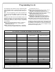
Programming instructions


10
NOTE:
The AL-PCI cable is designed to be used on a 9 pin serial COM port. If your computer has a 25 pin COM port, a 25 pin to 9 pin adapter must be used.
Warning: Polarity MUST be observed when connecting cables to the lock. The tab (-) must plug into the negative (black) hole.
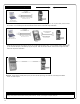
Scenario 4 Use the AL-IR1 Infrared printer to print your lock’s audit trail (event log), User Code list, clock settings and software
version. No cable required.
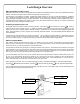
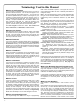
Scenario 1 Create the program in DL-Windows on your computer, then transfer the program from the computer directly to the lock via an
AL-PCI cable. You must always enter the User 298 User Code to send or receive data Using DL-Windows.
IBM COMPATABLE
LAPTOP OR DESKTOP PC
NOTE: OBSERVE TAB DIRECTION WHEN
INSERTING CABLE INTO LOCK
AL-PCI CABLE
CONNECT TO SERIAL PORT
(COM 1-4)
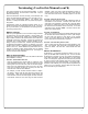
Scenario 2 Create the program in DL-Windows and transfer the program from your computer to an AL-DTM (via an AL-PCI cable)…then
transfer the program from the AL-DTM to the lock(s) (via a double-ended mini banana plug). The hand-held AL-DTM is useful because
you do not have to transport (or find electricity for) your computer. Data can also flow in reverse, from the lock, through the AL-DTM,
back to the computer for examination.
IBM COMPATABLE
LAPTOP OR DESKTOP PC
NOTE: OBSERVE TAB DIRECTION WHEN
INSERTING CABLE INTO LOCK
AL-PCI CABLE
CONNECT TO SERIAL PORT
(COM 1-4)
AL-DTM DATA
TRANSFER
MODULE
NOTE: OBSERVE TAB DIREC-
TION WHEN INSERTING CABLE
INTO AL-DTM AND LOCK
DOUBLE-ENDED MINI BANANA
PLUG CONNECTOR
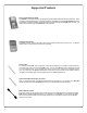
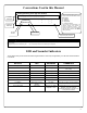
Product Communication Examples
Send to lock
Receive from lock
DL3200
DL3200
DL3200
AL-IR1 PRINTER