RMDC Series Installation Instructions 52-376 Rev B01 Rack Mount DC Power Supplies Operating and Installation Instruction Manual Includes PS5-M Power Supplies & FAI Accessory Boards MEA Approved AlarmSaf, Inc. 65A Industrial Way, Wilmington, Massachusetts 01887 978-658-6717 800-987-1050 www.alarmsaf.
RMDC Series Installation Instructions 52-376 Rev B01 2 MODEL NUMBERS THIS MANUAL COVERS MODEL NUMBERS: RMDC-PS5-M, RMDC-PS5-M-UL-FAI, RMDC-1248(F), RMDC-PS5-M-8(F)-UL-FAI, RMDC-PS5-MD, RMDC-PS5-MD-UL-FAI, RMDC-12416(F), RMDC-PS5-MD-16(F)-UL-FAI Full product list available at www.alarmsaf.com TABLE OF CONTENTS Warnings and Notices ..................................................................2 Introduction..................................................................................
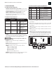
RMDC Series Installation Instructions 52-376 Rev B01 3 RMDC MODEL DESCRIPTIONS SINGLE VOLTAGE SYSTEMS All single voltage systems use one power supply, user selectable for 12VDC, 8A or 24VDC, 4A. RMDC-PS5-M: Single voltage, single output system. RMDC-PS5-M-UL-FAI: Single voltage system with FAI accessory module provides a single uncontrolled output and a single FAI controlled output. RMDC-1248(F): Single voltage system with eight (8) power distributed outputs.
RMDC Series Installation Instructions 52-376 Rev B01 4 SECTION I: ELECTRICAL RATINGS & SPECIFICATIONS Electrical Ratings SINGLE SUPPLY DUAL SUPPLY PTC Output Fuse Output PTC Output Fuse Output 120VAC 50-60Hz 170 Watts Maximum 340 Watts Maximum 8A @ 12V, 4A @ 24V 8A @ 12V, 4A @ 24V - Per Supply 1.6A/Output 3A/Output 1.6A/Output 3A/Output 85% ˜ <0.25% Typical, <0.
RMDC Series Installation Instructions 52-376 Rev B01 1.2 TERMINAL DESCRIPTIONS The terminal strips are located on the back panel of the unit. All terminal strips are removable with locking screws and accept wire sizes from 14-26AWG. Wire should be sized appropriately for voltage drop and current carrying capability. All terminals are labeled for polarity where appropriate. 1.2.1 AC Input 120VAC input: 3-wire line cord set included with unit. 1.2.
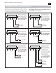
RMDC Series Installation Instructions 52-376 Rev B01 6 SECTION 2: INSTALLATION 2.1 MOUNTING 2.2 WIRING 2.1.1 Temperature and Humidity 2.2.1 Wire Routing Mount the unit in locations that meet the following temperature and humidity requirements. Do not expose to conditions outside of these ranges. All wiring must be installed in accordance with NFPA70 (NEC760) and all local code requirements. Power limited wiring requires that power limited and non-power limited wiring remain physically separated.
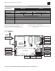
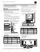
RMDC Series Installation Instructions 52-376 Rev B01 7 SECTION 3: OPERATION GRND FLT AC FLT NO NC C COM FLT NO NC C Before powering the system, the jumpers on the internal board(s) must be set for proper operation. Do not change jumper or switch settings while the unit is powered or damage to the system can occur. PS5-M Jumper and Switch Settings Each unit contains either one or two PS5-M boards. The voltage switch and jumpers on each board need to be configured for desired operation.
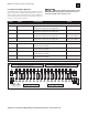
RMDC Series Installation Instructions 52-376 Rev B01 8 3.1.3 Front Panel Jumpers (Optional) Not all RMDC models have front panel jumpers. When present, these jumpers correspond to individual outputs and allow the selection of certain settings or functions depending on the model. RMDC units with front panel jumpers are listed below with settings. Models not listed do not have front panel jumpers ORDER# MODEL# Front panel jumpers must be set before initial power-up.
RMDC Series Installation Instructions 52-376 Rev B01 3.2.3 Indicators On the (Optional) FAIM Board 3.2.1 External Visual Indicators Illuminated Circuit Breaker/Power Switch: the power switch illuminates red when it is in the ON position and power is present. Front Panel Indicators: all units except RMDC-PS5-M-UL, RMDC-PS5-M-UL-FAI, RMDC-PS5-MD-UL and RMDC-PS5-MD-UL-FAI have front panel LED indicators. Each output has one LED which illuminates when voltage is available at that output terminal. 3.2.
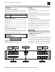
RMDC Series Installation Instructions 52-376 Rev B01 10 APPENDIX A: FAI INPUT CONNECTION METHODS Warnings and Notices The RMDC series can be ordered with an optional FAI input to disable the power to selected outputs upon activation of the FAI input.
RMDC Series Installation Instructions 52-376 Rev B01 11 APPENDIX C: ENCLOSURE CAD DRAWING Warnings and Notices 3.25” 18.80” 9.94” 1.20” 0.75” 1.20” 0.75” 0.68” 3.25” 0.82” 16.87” 0.38” 0.38” DETAIL “A” TYPICAL 4 PLACES 0.25” + AlarmSaf, Inc. 65A Industrial Way, Wilmington, MA 01887 978-658-6717 www.alarmsaf.com Ø 0.
RMDC Series Installation Instructions 52-376 Rev B01 12 TROUBLESHOOTING Installation and service should be performed only by a qualified service person and conform to all local codes CONDITION Power supply output voltage(s) incorrect or not present POSSIBLE CAUSE Power switch off or AC trouble Tripped input circuit breaker Excessive loading Bad or incorrect battery set The internal PS5-M has shut down Voltage not present at one or more of the power distribution outputs Internal problem Blown output fu
RMDC Series Installation Instructions 52-376 Rev B01 13 GLOSSARY ABC See “Accessory Board Connector.” Accessory Board Connector Connector on some AlarmSaf power supplies and accessory boards, allowing plug-in expansion of the system. Accessory Board AlarmSaf product used with AlarmSaf power supplies having an ABC connector. These boards allow plug-in expansion of system functionality.