RMBE Series Rack Mount Battery Enclosure Operating and Installation Instructions 52-342 Rev A.
Rack Mount Battery Enclosure Installation Instructions 5/27/2009, 11:42:41 AM Warnings and Notices WARNING - To reduce the risk of fire or electric shock, do not expose this product to rain or moisture WARNING - This installation and all servicing should be made by a qualified service person and should conform to all local codes NOTICE - This equipment shall be installed in a manner which prevents unintentional operation from employees, janitors and cleaners working about the premesis, by fallin
Rack Mount Battery Enclosure Installation Instructions 5/27/2009, 11:42:41 AM Table of Contents Section I. Warnings and Notices Page 2 1 Introduction 4 2 Applicable Standards / Documents 5 3 System Overview 3.1 Electrical Ratings and Specifications 3.2 Terminal Descriptions 5 5 6 4 Installation 4.1 Mounting 4.2 Wiring 7 7 9 5 Operating the RMBE Series 5.1 Jumper Configuration 5.2 Troubleshooting 10 10 11 6 Specifications 6.1 Electrical Specifications 6.2 Temperature Specifications 6.
Rack Mount Battery Enclosure Installation Instructions 5/27/2009, 11:42:41 AM Section 1 Introduction The AlarmSaf RMBE Rack Mount Battery Enclosure provides one or two 12VDC or 24VDC battery outputs in a standard 19” rack mountable enclosure. The enclosure contains two independent battery sets consisting of two 7AH batteries each. The two sets can also be paralleled for a single battery set of increased capacity.
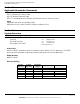
Rack Mount Battery Enclosure Installation Instructions 5/27/2009, 11:42:41 AM Section 2 Applicable Standards / Documents NFPA Standards NFPA 72 National Fire Alarm Code NFPA 70 National Electrical Code NFPA 731 Standard for the Installation of Electronic Premises Security Systems Other Applicable Local and State Building Codes Requirements of the Local Authority Having Jurisdiction (LAHJ) Section 3 System Overview 3.
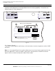
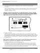
Rack Mount Battery Enclosure Installation Instructions 5/27/2009, 11:42:41 AM 3.2 Terminal Descriptions All terminal strips are removable with locking screws and accept wire sizes from 12-26AWG. Wire should be sized appropriately for voltage drop and current carrying capability. All terminals are labeled for polarity where appropriate.
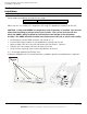
Rack Mount Battery Enclosure Installation Instructions 5/27/2009, 11:42:41 AM Section 4 Installation 4.1 Mounting 4.1.1 Mount the unit in locations that meet the following temperature and humidity requirements. Do not expose to conditions outside of these ranges. Temperature Humidity 0 °C to 49 °C (32 °F to 120 °F) 32 °C (90 °F) @ 93% Mount the unit in a standard 19" equipment rack using the appropriate hardware for the rack. CAUTION - A fully loaded RMBE can weigh more than 31 pounds, as installed.
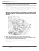
Rack Mount Battery Enclosure Installation Instructions 5/27/2009, 11:42:41 AM 1. Note the positions of the configuration jumpers on the back panel of the enclosure and remove all jumpers. Remove any terminal strips with wiring connected. 2. If the enclosure is installed in a rack, remove the four mounting screws and carefully slide the unit out of the rack. 3. Remove the six screws holding the enclosure’s top cover in place and remove the top cover. 4.
Rack Mount Battery Enclosure Installation Instructions 5/27/2009, 11:42:41 AM 4.2 Wiring 4.2.1 Wire Routing All wiring must be installed in accordance with NFPA70 [NEC760] and all local code requirements. Power Limited wiring requires that power limited and nonpower limited wiring remain physically separated. All power limited circuits must remain at least one quarter inch (¼") away from any nonpower limited circuit wiring. CAUTION - A lead-acid or gel cell battery can supply large amounts of current.
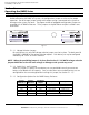
Rack Mount Battery Enclosure Installation Instructions 5/27/2009, 11:42:41 AM Section 5 Operating the RMBE Series 5.1 Jumper Configuration 5.1.1 Configuration Jumper Settings Before connecting the RMBE to a system, the configuration jumpers must be set for proper operation. Do not change jumper settings while output wiring is connected to the system or damage to the system may occur. The proper number of pluggable configuration jumpers are provided with all RMBE enclosures.
Rack Mount Battery Enclosure Installation Instructions 5/27/2009, 11:42:41 AM 5.
Rack Mount Battery Enclosure Installation Instructions 5/27/2009, 11:42:41 AM Section 6 Specifications 6.1 Electrical Specifications 6.1.1 Output Voltage 6.1.2 Amphour Capacity 6.1.3 Overcurrent Protection 6.1.4 Maximum Operating Current 12VDC or 24VDC Nominal Varies - See Section 5.1.1.3 9A at 24V, 18A at 12V per battery set 8 amperes 6.2 Temperature Specifications 6.2.1 Ambient Temperature Range 6.2.2 Ambient Humidity 6.2.
Rack Mount Battery Enclosure Installation Instructions 5/27/2009, 11:42:41 AM 9.940" 3.250" 6.3.3 CAD Drawing 18.880" 1.203" 1.202" 16.87" 0.75" 0.815" 3.71" 3.249" 0.683" 0.752" 0.375" DETAIL “A” TYPICAL 4 PLCS .25" 0.375" Ø .1875” Ø .1875” DETAIL “ A “ 52-342 Rev A.01 Page 13 of 14 AlarmSaf 65A Industrial Way, Wilmington, MA 01887 978 658 6717 www.alarmsaf.
Glossary 5/27/2009, 11:42:41 AM Glossary ABC See “Accessory Board Connector” Accessory Board Connector Connector present on some AlarmSaf power supplies and accessory boards, allowing plug-in expansion of the system Accessory Board An AlarmSaf product for use with AlarmSaf power supplies containing an ABC connector. These boards allow plug-in expansion of the functionality of the system.