RMMV Series Rack Mount AC/DC Power Supply Operating and Installation Instructions 52-391 Rev A.
RMMV Series Installation Instructions 7/13/2009, 10:26:56 AM Warnings and Notices WARNING - To reduce the risk of fire or electric shock, do not expose this product to rain or moisture WARNING - This installation and all servicing should be made by a qualified service person and should conform to all local codes NOTICE - This equipment shall be installed in a manner which prevents unintentional operation from employees, janitors and cleaners working about the premesis, by falling objects, by cus
RMMV Series Installation Instructions 7/13/2009, 10:26:56 AM Table of Contents Section I. Warnings and Notices Page 2 1 Introduction 4 2 Applicable Standards / Documents 5 3 System Overview 3.1 Electrical Ratings and Specifications 3.2 Terminal Descriptions 3.3 Fusing 6 6 7 8 4 Installation 4.1 Mounting 4.2 Wiring 9 9 10 5 Operating the RMMV Rack Mount Power Supply 5.1 Jumper Configuration 5.2 Visual Indicators 5.3 Troubleshooting 11 11 13 15 6 Specifications 6.1 Electrical Specifications 6.
RMMV Series Installation Instructions 7/13/2009, 10:26:56 AM Section 1 Introduction The RMMV series of rackmount power supplies provides either 24 or 28 VAC for powering CCTV or similar low voltage AC operable equipment AND 12 and 24VDC for powering access control or similar DC equipment. The units are intended for mounting within a standard nineteen inch electronics rack and may not be exposed to rain, moisture, or temperature conditions outside the stated range of operation.
RMMV Series Installation Instructions 7/13/2009, 10:26:56 AM Section 2 Applicable Standards / Documents NFPA Standards NFPA 72 National Fire Alarm Code NFPA 70 National Electrical Code US Standards UL 294 Access Control System Units UL 1076 Proprietary Burglar Alarm Units and Systems UL 1481 Power Supplies for Fire Protective Signaling System UL 2044 Commercal Closed-Circuit Television Equipment Canadian Standards ULC S318 Standard for Power Supplies for Burglar Alarm Systems ULC S527 Standard for Control
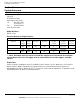
RMMV Series Installation Instructions 7/13/2009, 10:26:56 AM Section 3 System Overview 3.1 Electrical Ratings and Specifications Manufactured By AlarmSaf 65A Industrial Way Wilmington, MA 01887 Tel: 800 987 1050 978 658 6717 Fax: 978 658 8638 www.alarmsaf.com Model Numbers RMMV Series Electrical Ratings and Specifications Fuse Protected Products Model # RMMV-122428-24F RMMV-122428-24 Nominal Input Voltage 120 VAC Max Input Current 4.2 Amp 120 VAC 4.
RMMV Series Installation Instructions 7/13/2009, 10:26:56 AM 3.2 Terminal Descriptions All terminal strips are removable with locking screws and accept wire sizes from 12-26AWG. Wire should be sized appropriately for voltage drop and current carrying capability. All terminals are labelled for polarity or phasing where appropriate.
RMMV Series Installation Instructions 7/13/2009, 10:26:56 AM 3.2.6 Fault Outputs (Common Fault / AC Fault) Form C Contacts Contacts rated at 1A @ 24VDC, 0.5A @ 120VAC Fault relays employ “fail-safe” operation and are powered in a non-fault condition (connection between common and NO when no fault exists) Each internal supply has independent sets of fault contacts 3.2.7 Distributed AC Outputs Each distributed output is individually over-current protected (3A for fuse protected units, 1.
RMMV Series Installation Instructions 7/13/2009, 10:26:56 AM Section 4 Installation 4.1 Mounting 4.1.1 Mount the unit in locations that meet the following temperature and humidity requirements. Do not expose to conditions outside of these ranges. Temperature Humidity 0 °C to 49 °C (32 °F to 120 °F) 32 °C (90 °F) @ 93% Mount the unit in a standard 19" equipment rack using the supplied 10-32 X ¾" machine scre ws.
RMMV Series Installation Instructions 7/13/2009, 10:26:56 AM 4.2 Wiring 4.2.1 Wire Routing All wiring must be installed in accordance with NFPA70 [NEC760] and all local code requirements. Power Limited wiring requires that power limited and nonpower limited wiring remain physically separated. All power limited circuits must remain at least one quarter inch (¼") away from any nonpower limited circuit wiring. 4.2.
RMMV Series Installation Instructions 7/13/2009, 10:26:56 AM Section 5 Operating the RMMV Rack Mount Power Supply 5.1 Jumper Configuration 5.1.1 AC Zones Each individual AC output zone may be configured for a 24VAC or 28VAC output. The output setting is controlled by the movable jumper plugs behind the front panel (JP1-JP16). The upper setting (V2) is for a 28VAC output, the lower setting (V1) is for a 24VAC output.
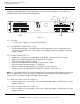
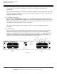
RMMV Series Installation Instructions 7/13/2009, 10:26:56 AM AC PRESENCE VISUAL INDICATOR BAT EARTH GND DETECT DETECT AC ON EARTH GOUND DETECTION ENABLE VOLTAGE SELECT 12V BATTERY PRESENCE DETECTION ENABLE 24V OUTPUT VOLTAGE SELECT SWITCH Figure 5.2.1.1 5.1.2.1.1.2 Jumper Settings For proper operation, the jumpers on the internal PS5-M should be set appropriately. These jumpers may be set with the unit powered or unpowered.
RMMV Series Installation Instructions 7/13/2009, 10:26:56 AM 5.1.2.1.2 SPS4 Jumper Settings The SPS4 has two jumpers for setting its output voltage. It is factory set for 12VDC out. If a different voltage is required, the jumpers must be changed as follows: Voltage Output 5VDC 12VDC 5-18VDC Adjustable* JP1 Left Left Right JP2 Left Right Left * - When using the adjustable range, adjust the output voltage using potentiomer R5 5.2 Visual Indicators 5.2.1 External Visual Indicators 5.2.1.
RMMV Series Installation Instructions 7/13/2009, 10:26:56 AM 5.2.2.1.3 AC FLT This LED illuminates when the AC input voltage falls below approximately 85% of the nominal input voltage setting. 5.2.2.1.4 COM FLT This LED illuminates on any of the following conditions: High or Low Battery Voltage High or Low Output Voltage Missing / Damaged Battery Earth Ground Fault Fault received on ABC connector 5.2.2.1.
RMMV Series Installation Instructions 7/13/2009, 10:26:56 AM 5.3 Troubleshooting WARNING - Installation and service should only be performed by a qualified service person and should conform to all local codes 5.3.
RMMV Series Installation Instructions 7/13/2009, 10:26:56 AM AC trouble Bad / Incorrect Battery Set The internal PS5-M has shut down Blown battery fuse on the internal PS5-M Excessive loading on output The Common Fault relay is indicating a fault condition Improper ABC cable connection to the internal PS5-M Bad, Incorrect, or Missing Battery Set Earth Ground Fault Internal problem The AC Fault relay is indicating a fault condition Low or Missing AC Blown AC fuse on the internal PS5-M Battery not
RMMV Series Installation Instructions 7/13/2009, 10:26:56 AM Section 6 Specifications 6.1 Electrical Specifications 6.1.1 Input Voltage 6.1.2 Input Power 6.1.3 Input Frequency 6.1.4 Minimum Battery Charge Capacity 6.1.5 Maximum Battery Charge Capacity 6.1.6 Maximum Battery Charge Current 6.1.7 Maximum Battery Standby Current 6.1.8 DC Output Zones 6.1.9 AC Output Zones 6.1.10 Zone Output Current 6.1.11 Total DC Output Current 6.1.
RMMV Series Installation Instructions 7/13/2009, 10:26:56 AM Wiring and using an RMBE Series Battery Enclosure with the RMMV The RMBE Series of Battery Enclosures provides battery backup in a standard 19 inch 2RU rack mountable enclosure. It can be configured for single or dual output. Each output can be configured for either 12 or 24VDC. Configuration of the RMBE series is by pluggable jumpers on the back panel of the enclosure.
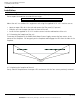
RMMV Series Installation Instructions 7/13/2009, 10:26:56 AM Power Supply 1 Power Supply 2 B A B OUT 16 A B OUT 15 A B OUT 14 A B OUT 13 A B OUT 12 A B OUT 11 A B OUT 10 OFF RESET A ON OUT 9 BAT COM FLT AC FLT NO NC C NO NC C 24V DC - + - +- + - 12V DC +- + To reduce the risk of fire, replace interior fuses only with same type and rating AC POWER B A B OUT 8 A B OUT 7 A B OUT 6 A B OUT 5 A B OUT 4 A B OUT 3 A B OUT 2 CAUTION RISK OF ELECTRICAL SHOCK DO
Glossary 7/13/2009, 10:26:56 AM Glossary ABC See “Accessory Board Connector” Accessory Board Connector Connector present on some AlarmSaf power supplies and accessory boards, allowing plug-in expansion of the system Accessory Board An AlarmSaf product for use with AlarmSaf power supplies containing an ABC connector. These boards allow plug-in expansion of the functionality of the system.