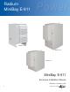
Radium MiniBay E-911 RMB-E-911-A48 RMB-E-911-B RMB-E-911-C MiniBay E-911 Enclosure Installation Manual Effective: October, 2004 ® 031-171-C0-003 Rev.
Power Alpha Technologies 2 ® 031-171-C0-003 Rev.
Power Systems MiniBay E-911 Enclosure Installation Manual 031-171-C0-003 Rev. C — © 2004 Alpha Technologies Photographs contained in this manual are for illustrative purposes only. These photographs may not match your installation. Operator is cautioned to review the drawings and illustrations contained in this manual before proceeding. If there are questions regarding the safe operation of this powering system, please contact Alpha Technologies or your nearest Alpha representative.
Power Systems Table of Contents Document Review History ................................................................................... 6 Important Safety Instructions ............................................................................... 7 1.0 Overview .................................................................................................. 12 1.1 1.2 1.3 The MiniBay E-911 Series Enclosures ....................................................................
Power Systems List of Figures 1.0 Overview .................................................................................................. 12 Fig. 1-1 Fig. 1-2 Fig. 1-3 Fig. 1-4 Fig. 1-5 MiniBay RMB-E-911-A48 and -B Cabinets (front view) ............................................. 12 MiniBay RMB-E-911-C Enclosure (front and rear views) .......................................... 13 System Wiring Schematic ‘A48’ Configuration ........................................................
Document Revision History Document Name Control/Rev. Number Radium MiniBay E-911 Enclosure Installation Manual “ 031-171-C0-001 Rev. A “ 6 031-171-C0-002 Rev. B Updated dual bus wire labeling and schematic, pages 16 & 18. 031-171-C0-003 Rev. C Added revision history, page 6. Release Date September 16, 2004 October 5, 2004 031-171-C0-003 Rev.
Important Safety Instructions Review the drawings and illustrations contained in this manual before proceeding. If there are any questions regarding the safe installation or operation of the system, contact Alpha Technologies or the nearest Alpha representative. Save this document for future reference.
General Safety Precautions This enclosure and its associated hardware (power supply, batteries, cabling) may contain equipment, batteries or parts which have accessible hazardous voltage or currents. To avoid injury: • • • • • • • • • • • • • 8 This enclosure and its associated hardware must be serviced only by authorized personnel. Enclosure must remain locked at all times, except when authorized service personnel are present.
Enclosure, equipment or parts may be damaged or cause damage if used or installed improperly. To avoid damage: • • • • • • • Prior to installation, verify that the AC input voltage to the enclosure and its equipment match with respect to voltage and frequency. Prior to installation, verify that the output voltage from the enclosure or its equipment match the voltage requirements of the connected equipment (load).
Battery Safety Notes, cont. • • • • • • • • • Neutralize any spilled battery emission with the special solution contained in an approved spill kit or with a solution of 1 lb. Bicarbonate of soda to 1 gal of water. Report chemical spill using your company’s spill reporting structure and seek medical attention if necessary. Always replace batteries with those of an identical type and rating. Never install old or untested batteries. Do not charge batteries in a sealed container.
Recycling and Disposal Instructions Spent or damaged batteries are considered environmentally unsafe. Always recycle used batteries or dispose of the batteries in accordance with all federal, state and local regulations. Electrical Safety • • • • • • Lethal voltages are present within the power supply and electrical boxes. Never assume that an electrical connection or conductor is not energized.
1.0 Overview and Specifications 1.1 The MiniBay E-911 Series Enclosures The Federal Communications Commission (FCC) created the Enhanced 911 program to improve the effectiveness of the national 911 wireless system. The second part of this two-phase effort requires wireless carriers to provide location information of all wireless 911 calls.
1.0 Overview and Specifications, cont. Air Conditioner Control Board 19" Swing-Away equipment rack Punch-Down panel DC Distribution panel DC to DC converter Air Conditioner Breaker Intrusion alarm switch 7" Riser Intrusion alarm switch Alarm Interface Ground Bar Roxtec Panel Input 48VDC (+) and (-) Fig. 1-2, MiniBay RMB-E-911-C Enclosure (front and rear views) 031-171-C0-003 Rev.
1.2 RMB-E-911 System Specifications 1.2.1 RMB-E-911-A48 Radium MiniBay RMB-E-911-A48 Specifications Radium MiniBay Equipment Section Swing Rack MiniBay “C” Channel/Riser MiniBay “C” Channel/Riser Hardware Kit Dual Term Bar Kit Ground Bar Kit, Intrusion Sensor Kit Enclosure Insulation Kit Cable Entry Port Blank Knockout Panel Enclosure Cable Port Blank Alarm Terminal Interface Board 50-Pair 66-Block (Alarm Terminations) Key to enclosure doors Thermal Mgmt.
1.2 RMB-E-911 System Specifications, cont. 1.2.
1.2 RMB-E-911 System Specifications, cont. 1.2.
1.3 System Wiring Schematics 1.3.1 ‘A48’ Configuration Radium MiniBays arrive at their destination with all internal components preassembled and installed in the enclosure. The following diagram will help the installer/engineer to understand the wiring schematic of the RMB-E-911 enclosures.
1.3 System Wiring Schematics, cont. 1.3.2 ‘B’ Configuration Radium MiniBays arrive at their destination with all internal components preassembled and installed in the enclosure. The following diagram will help the installer/engineer to understand the wiring schematic of the RMB-E-911 enclosures.
1.3 System Wiring Schematics, cont. 1.3.3 ‘C’ Configuration Radium MiniBays arrive at their destination with all internal components preassembled and installed in the enclosure. The following diagram will help the installer/engineer to understand the wiring schematic of the RMB-E-911 enclosures.
2.0 Site Preparation 2.1 General Information Description This document describes the installation procedures for the RMB-E-911-B and -C enclosures. The process of installing the enclosure(s) are broken into four discrete procedures. If viewing this document on-line, click a section below (blue text) to jump directly to it. • • • • 2.
2.0 Site Preparation, cont. 2.3 Site Selection Prior to installation, you must decide on the location, mounting platform, and connection/grounding options available for the MiniBay enclosure. The information in this section will help familiarize you with these options and methods. Considerations • • • • • • • • Where possible, select a site that is above the 100 year flood plain, and away from houses. Place in a shaded location to minimize the effects of solar loading.
2.0 Site Preparation, cont. 2.4 Polymer Precast Pad (optional) If you install the Polymer Precast Pad, you will need to prepare a layered bed of sand and gravel before placing the pad on top. For specific information, consult the instructions that accompany the Precast Pad. Fig. 2-2, Polymer Precast Pad for Single-wide Enclosure 3” H X 42” W X 44” D P/N 641-110-10 3.00" min. SYMM. 44.00 SYMM. 32.00 FRONT OF PAD STAINLESS STEEL HARDWARE SUPPLIED WITH PAD SYMM. 24.00 SYMM. 25.82 SYMM. 30.00 SYMM.
2.0 Site Preparation, cont. 2.5 Pour-in-Place Pad Frame Pad Frame Template The illustration below shows the overall size of the pad frame template for a single MiniBay enclosure. The actual outer dimensions of the pad will be determined by the customer's requirements. When placing the pad, allow at least 40” of clearance for the front enclosure door to fully open. The four 1/2” bolts provided with the frame should remain installed to prevent debris from fouling the threads. See p.
2.0 Site Preparation, cont. 2.6 Enclosure Grounding Alpha provides the following grounding method as a suggestion for sites not equipped with accessible grounding facilities. Grounding Specifications • Configure enclosure footprint to accommodate swing arc of enclosure door. See Fig. 2-1. • • • 1/2" x 8' copper ground rod, four places, driven about 2 feet (typical) from the corners of the pad. #6 bare copper wire loop terminated to each ground rod and buried a minimum of 30 inches below grade.
3.0 Installation 3.1 Lifting If arranging block and tackle to lift the enclosure, use the following standard rule: Make the length of the cable between the eyebolts and the lifting hook at least twice the distance between the lifting plates (2 X 32” = 64”). This will ensure that the lifting angle of the chain is greater than 60 degrees. After the enclosure is in place, the lifting plates may be removed or left in place. The lifting plate fasteners are sealed to prevent water intrusion or seepage.
3.0 Installation, cont. 3.2 Enclosure Installation The RMB-E-911 is provided with either a 7” riser or 14” riser/battery module. These two configurations require somewhat different mounting considerations and procedures. The 7” riser is shipped loose (not bolted to the enclosure) for use as a template to mark the pad for hardware and position. Mounting holes are provided in the base of the battery compartment or riser to accommodate the pad’s anchor bolts.
3.0 Installation, cont. 3.2 Enclosure Installation, cont. Installation Procedure, ‘B’ Configuration Remove all packing material from the enclosure and inspect for damage. Continue with the following steps: 1. Unwrap the pallet and remove the battery drawer covers. Reposition the lifting eyes to accept cabling. 2. Position the enclosure on the pad and use as template to mark drilling locations. Ensure the pad is smooth, level and free of bumps. 3.
3.0 Installation, cont. 3.3 Air Conditioner Overview 3.3.1 Basic Theory of Refrigeration: 1. Low pressure gas is drawn into the compressor pump, and compressed into a high pressure gas. The compression of the gas creates heat. 2. The heated high pressure gas is sent through a coil called a condenser. Air is blown over the coil, cooling the gas into a liquid. 3. The high pressure liquid passes through an expansion valve, where the liquid is allowed to expand and boil off into a gas.
3.0 Installation, cont. 3.3.2 Air Conditioner Control Board The air conditioner control board (see below) has multiple functions for compressor, condenser fan and alarm control. It has remote temperature sensors that monitor compressor discharge and evaporator suction line temperature. It has a board-mounted temperature sensor to monitor the enclosure temperature, or optional remote temperature sensor to monitor a specific area in the enclosure. The board incorporates and L.V.
3.0 Installation, cont. 3.3.
3.0 Installation, cont. 3.3.4 Air Conditioner Control Card Jumper Settings Temperature Setpoint Jumper 104°F/40°C 40° C Maximum Internal Temp. 38° C Startup 95°F/35°C 38° C Setpoint 34° C Shutdown 33° C Startup 86°F/30°C 33° C Setpoint 29° C Shutdown 28° C Startup 77°F/25°C 28° C Setpoint 24° C Shutdown 23° C Startup 68°F/20°C 23° C Setpoint 19° C Shutdown 18° C Startup 59°F/15°C System Setpoint Jumper This jumper determines what temperature the system will maintain inside the enclosure.
3.0 Installation, cont. 3.4 Roxtec Panel Assembly Instructions The illustrations below are a generic overview of the operation of the Roxtec panel. For detailed instructions, please refer to the manufacturer’s instructions included with the panel. 1 2 3 4 5 6 7 8 9 10 11 max 8 Nm The Roxtec block panel is designed to allow rotation, as shown below. It can also be moved to the opposite side of the enclosure if required by site design.
3.0 Installation, cont. 3.5 19” Swing Rack and Equipment Installation The 19” swing rack can swing 90° to the left to allow access to the cables and rack-mounted equipment. It is grounded to the enclosure. 1 2 3 To swing the rack, loosen the captive securing bolts at the top and bottom right corners and swing the rack to the left. When installing equipment in the rack, provide a long enough service loop to prevent damage to cables when swinging the rack open.
3.0 Installation, cont. 3.6 Battery Installation (RMB-E-911-B) 1 Remove the front battery enclosure cover and set aside. 2 Slide the battery tray towards the front of the enclosure until the tray locks into place. 3 Place two Marathon ‘M’ series batteries onto the battery tray with the connections facing out. 4 Wire in accordance with the diagram below. Marathon ‘M’ Series Battery 100A Fuse Bolt NEG POS M12V40F NEG POS M12V40F Max torque is 75 in. lbs., +/- 3 in. lbs.
3.0 Installation, cont. 3.7 24VDC Power Connections (RMB-E-911-C) 24 VDC is distributed through the breaker panel above the DC to DC converter. +24 VDC is available at the bus bars on either end of the breaker panel. A 24VDC ground is located on the enclosure ground bar on the right door jam of the enclosure. Refer to the operator’s manual for the Argus DC-to-DC converter, . +24VDC Output #1 24VDC Input +24VDC Output #2 Enclosure Ground Bar (24VDC Neg) Fig.
3.0 Installation, cont. 3.8 Service Power Connections (RMB-E-911-B) The service power breaker box is located in the rear of the enclosure on the right hand wall. the breaker box should be wired following all local codes and regulations. Fig. 3-8, Service Power Breaker box (RMB-E-911-B) 36 031-171-C0-003 Rev.
3.0 Installation, cont. 3.9 48VDC Power Connection (RMB-E-911-C and -A48) 48VDC should be brought into the enclosure through the Roxtec panel or enclosure base. Enclosure Ground Bar Roxtec Panel 48VDC Input Bar Fig. 3-9, 48VDC Connections (RMB-E-911-C and -A-48) 031-171-C0-003 Rev.
4.0 Appendix A CSA Marks CSA International (CSA) was established in 1919 as an independent testing laboratory in Canada. In 1994, OSHA granted CSA Nationally Recognized Testing Laboratory (NRTL) status in the United States of America. This was extended in 1999. The specific notifications were posted on OSHA’s official Web site as follows: ® NRTL/C www.osha-slc.gov/fedreg_osha_data/fed19940809.html www.osha-slc.gov/fedreg_osha_data/fed19991104.
Power Alpha Technologies ® Alpha Technologies 3767 Alpha Way Bellingham, WA 98226 USA Tel: (360) 647-2360 Fax: (360) 671-4936 Web: www.alpha.com Alpha Technologies Ltd. 4084 McConnell Court Burnaby, BC, V5A 3N7 CANADA Tel: (604) 430-1476 Fax: (604) 430-8908 Alpha Technologies Europe Ltd.